HYBRID BATTERY SYSTEM
-
CONSTRUCTION
-
The HV battery mainly consists of the HV battery (5 battery stacks), No. 1 to No. 5 HV battery voltage detection wire, HV battery junction block assembly, battery cooling blower assembly, battery ECU assembly and service plug grip.
-
The HV battery uses plastic container type cells. As a result, high power density, lightweight construction, and longevity have been accomplished at high levels.
-
The battery cooling blower assembly is used as a dedicated cooling system to ensure that the HV battery performs properly, despite it generating significant heat during the repetitive charge and discharge cycles.
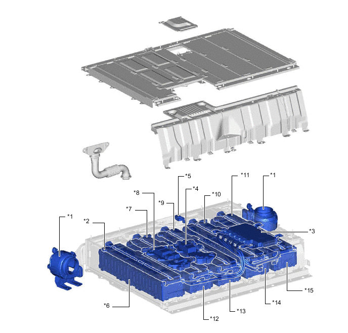
*1 Battery Cooling Blower Assembly *2 No. 1 HV Battery Voltage Detection Wire *3 Battery ECU Assembly *4 No. 2 HV Battery Junction Block Assembly *5 Service Plug Grip *6 HV Battery Stack (No. 1 Battery stack) *7 No. 2 HV Battery Voltage Detection Wire *8 No. 1 HV Battery Junction Block Assembly *9 No. 3 HV Battery Voltage Detection Wire *10 No. 4 HV Battery Voltage Detection Wire *11 No. 5 HV Battery Voltage Detection Wire *12 HV Battery Stack (No. 2 Battery stack) *13 HV Battery Stack (No. 3 Battery stack) *14 HV Battery Stack (No. 4 Battery stack) *15 HV Battery Stack (No. 5 Battery stack) - - -
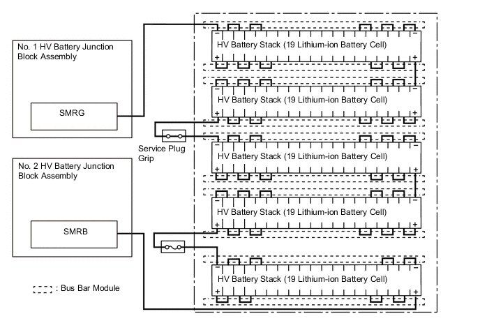
Compact, lightweight 3.7 V lithium-ion battery cells are used in order to generate high power output.

*1 Positive Terminal *2 Negative Terminal -
The 19 lithium-ion battery cells provided for each HV battery stack are connected in series in a bus bar module.
-
The HV battery consists of 5 HV battery stacks. They are connected to each other in series through bus bar modules and wiring harness.
-
No. 1 HV Battery Voltage Detection Wire to No. 5 HV Battery Voltage Detection Wire
-
3 thermistor type battery temperature sensors are provided in each the HV battery detection wires.
-
The thermistor type intake air temperature sensors is provided in No. 3 and No. 4 HV battery voltage detection wire to detect the temperature of the cooling air.
-
The battery ECU assembly optimally controls the cooling system so that the HV battery temperature can be within a specified range according to the temperature information.
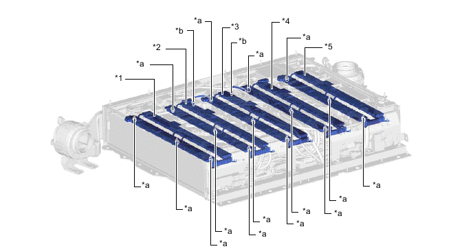
*1 No. 1 HV Battery Voltage Detection Wire *2 No. 2 HV Battery Voltage Detection Wire *3 No. 3 HV Battery Voltage Detection Wire *4 No. 4 HV Battery Voltage Detection Wire *5 No. 5 HV Battery Voltage Detection Wire - - *a HV Battery Temperature Sensor *b HV Battery Intake Air Temperature Sensor -
Battery Heater
-
The battery heater wire is sewn into a non-woven fabric which is laminated between insulating polycarbonate boards.
-
Each heater uses a different wiring pattern to evenly distribute heat to each HV battery cell when heating the battery.
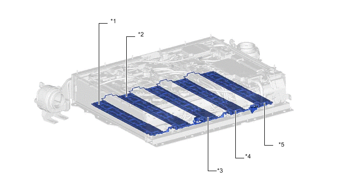
*1 Heater (for No. 1 Battery Stack) *2 Heater (for No. 2 Battery Stack) *3 Heater (for No. 3 Battery Stack) *4 Heater (for No. 4 Battery Stack) *5 Heater (for No. 5 Battery Stack) - -
-
-