HYBRID BATTERY SYSTEM
-
OUTLINE
-
A compact, lightweight and highly-efficient lithium-ion battery is used to the HV battery.
-
The HV battery which has a high power density, is lightweight and has a long lifespan, stores energy from both plug-in charging and regenerated power.
-
By optimizing the HV battery coolant passages, both quietness in the vehicle and HV battery cooling performance are ensured.
-
-
SPECIFICATION
-
HV Battery
Item Specification Type Lithium-ion Battery Cell Quantity 95 Cells (19 Cells x 5 Stacks) Nominal Voltage V 351.5 Battery Capacity (3HR) Ah 25
-
-
MAIN FEATURES
-
Cooling System
-
To ensure the proper performance of the HV battery while it generates heat during repetitive charge and discharge cycles, a dedicated cooling system is used for the HV battery.
-
An air filter has been provided on the cooling air intake bezel.
Note
-
Intake ports have been added to both sides of the rear seatback to provide cooling for the HV battery.
If the vent becomes blocked, the hybrid battery may overheat, leading to a reduction in hybrid battery output, and be damage.
-
Clean the air intake vent regularly using a vacuum cleaner to prevent the hybrid battery from overheating.
-
Do not get water or foreign materials in the air intake vent as this may cause a short circuit and damage the hybrid battery.
-
Do not carry large amounts of water such as water cooler bottles in the vehicle. If water spills onto the hybrid battery, the battery may be damaged.
-
-
Cooling air enters the chamber of each HV battery stack to cool the hybrid battery cells and is then discharged into the HV battery.Intake ports have been added to both sides of the rear seatback to provide cooling for the HV battery.
-
The cooling air that was discharged into the HV battery is discharged under the deck board.
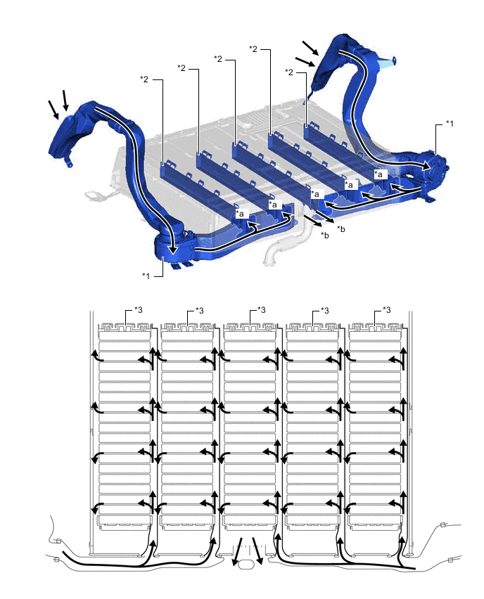
*1 Battery Cooling Blower Assembly *2 Chamber *3 HV Battery Stack - - *a to Battery Pack *b to Under No. 2 Rear Floor Board 
Cooling Air Flow - -
-
-
Service Plug Grip
-
By removing the service plug grip before performing any inspection or service, the high-voltage circuit is shut off, thus ensuring safety during service.
CAUTION:
-
A charge remains in the high-voltage capacitor in the inverter with converter assembly after the high-voltage circuits are cut off. When servicing a hybrid vehicle, after removing the service plug grip, wait at least 10 minutes to allow the capacitor to discharge before beginning work.
-
For further details on how to handle the service plug grip and other safety cautions, refer to the Repair Manual.
Note
-
The service plug grip should never be removed when the system is in the on (READY) state.
-
After removing the service plug grip, turning the power switch on (READY) may cause a malfunction. Do not turn the power switch on (READY) unless instructed by the Repair Manual.
-
-
The service plug grip is connected in the battery module circuit and is used for manually shutting off the high-voltage circuit. This ensures safety during service.
-
An interlock switch is provided on the service plug grip. When the grip section is unlocked, the interlock switch is turned off and the hybrid vehicle control ECU shuts off the system main relays. However, to ensure safety, make sure to turn the power switch off before removing the service plug grip.
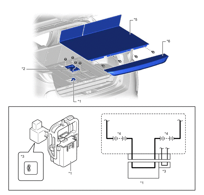
*1 Service Plug Grip *2 No. 4 EV Battery Shield Panel *3 Interlock Switch *4 HV Battery *5 No. 1 Rear Floor Board *6 No. 2 Rear Floor Board
-
-