BODY STRUCTURE
-
CONSTRUCTION
-
Body Shell
-
By optimizing the positioning of body structural members, optimizing the joining methods, and configuring reinforcement members, a lightweight and highly rigid body construction with excellent maneuvering stability has been achieved.
-
For the cowl top outer panel sub-assembly, by positioning the upper support (front suspension support sub-assembly) so it is connected in a straight line, the high lateral rigidity has been ensured, realizing excellent handling stability.
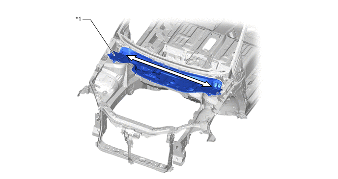
*1 Cowl Top Outer Panel Sub-assembly - - 
Linearization of Ridge Line - - -
By configuring the center frame crossmember sub-assembly between the left and right front side member sub-assemblies, torsional rigidity has been achieved, and superior handing stability has been realized.
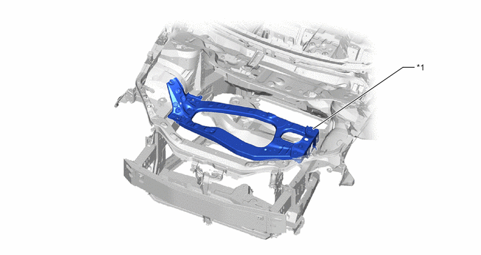
*1 Center Frame Crossmember Sub-assembly - - -
By configuring braces around the quarter wheel house panel sub-assembly, torsional rigidity has been achieved, and superior handing stability has been realized.
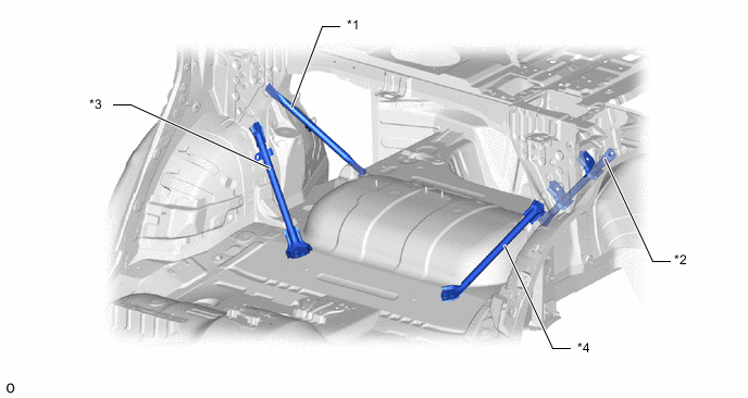
*1 No. 3 Body Mounting Bracket Sub-assembly RH *2 No. 3 Body Mounting Bracket Sub-assembly LH *3 Rear Floor Panel Brace Sub-assembly RH *4 Rear Floor Panel Brace Sub-assembly LH -
To reduce weight, the use of CFRTP (Carbon Fiber Reinforced Thermoplastic) has been maximized, allowing a rear frame assembly with ultralight frame construction to be employed.
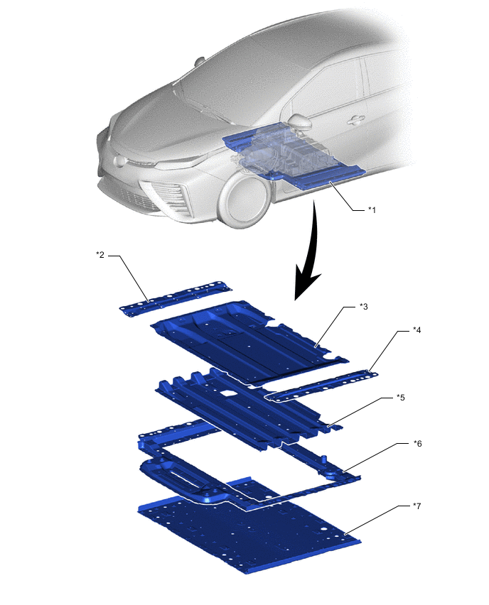
*1 Rear Frame Assembly *2 Frame Rear Crossmember Extension RH *3 No. 5 Frame Upper Crossmember *4 Frame Rear Crossmember Extension LH *5 Frame Center Crossmember *6 Frame Rear Crossmember Sub-assembly *7 No. 5 Frame Lower Crossmember - -
-
-
-