BODY STRUCTURE
-
FUNCTION
-
Impact Absorbing Structure for Frontal Collision
-
This design disperses collision loading from the front side member sub-assembly through the front torque box and into the rocker portion.
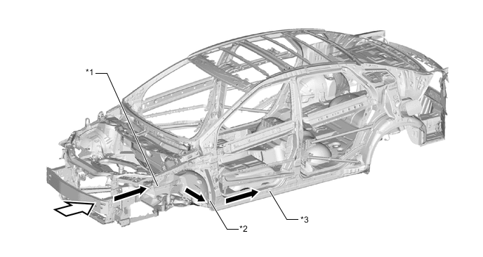
*1 Front Side Member Sub-assembly *2 Front Torque Box *3 Rocker Portion - - 
Impact 
Path to Collision Energy -
This design disperses collision loading from the front side member sub-assembly both through the inner torque brace to the side opposite the collision, and also through the underframe and rear frame assembly to the rear of the vehicle.
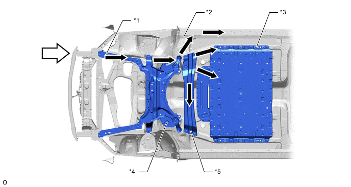
*1 Front Side Member Sub-assembly *2 Front Torque Box *3 Rear Frame Assembly *4 Front Suspension Crossmember Sub-assembly *5 Inner Torque Brace - - Impact Path to Collision Energy
-
-
Impact Absorbing Structure for Side Collision
-
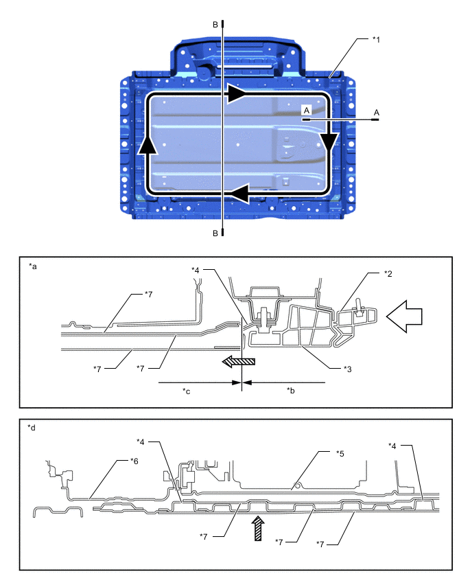
A floor side inner member made of high tensile strength steel plate, and a rocker inner reinforcement made of ultra-high tensile strength steel plate have been adopted, retaining strength against side collisions while also achieving reduced weight and simplified design.
-
In a side collision, the collision loading is transmitted through the floor side inner member and front seat adjuster rod, and through the front floor reinforcement center to the side opposite the collision, achieving a design that limits deformation of the cabin.
-
In the A section (indicated by *c in the illustration), the underbody employs a rear body support bracket reinforcement and rear crossmember extension frame (made of shock-absorbing aluminum material) for a design which provides efficient absorption of collision loading in a limited amount of space.
-
The design employs a rear frame assembly, and by transmitting collision loading to the opposite side of the vehicle, deformation of the FC stack assembly and passenger cabin is suppressed. Furthermore, by intentionally making the connection between the floor side inner member sub-assembly and front floor panel sub-assembly loose, deformation of the A section (*c in illustration) and B section (*d in illustration) can be isolated, providing a design in which deformation of the front floor panel sub-assembly center following a collision limits the energy transmitted to the FC stack assembly.
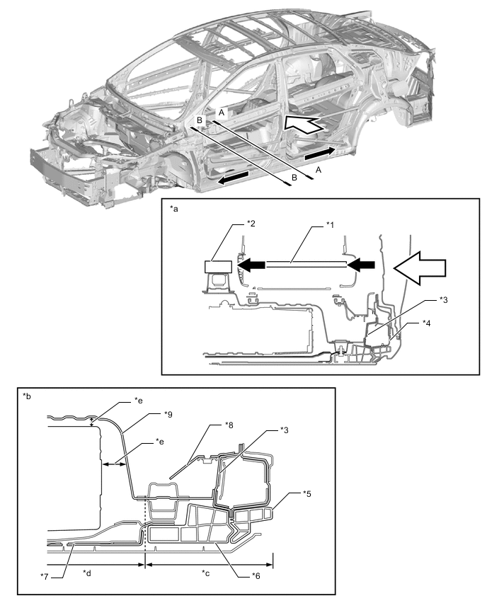
*1 Front Seat Adjuster Rod *2 Front Center Floor Reinforcement *3 Floor Side Inner Member Sub-assembly *4 Rocker Outer Reinforcement *5 Rear Body Support Bracket Reinforcement *6 Rear Crossmember Extension Frame *7 Rear Frame Assembly *8 Floor Side Inner Rail Sub-assembly *9 Front Center Floor Panel Sub-assembly - - *a A-A Cross Section *b B-B Cross Section *c A Section *d B Section *e Space - - Impact Path to Collision Energy
-
-
Impact Absorbing Structure for Rear Collision
-
To disperse the energy imparted by a rear offset collision, a large rear bumper reinforcement sub-assembly has been adopted. With this design, collision loading is dispersed to the left and right members, suppressing deformation of the cabin and also suppressing deformation of the No. 2 hydrogen tank assembly.
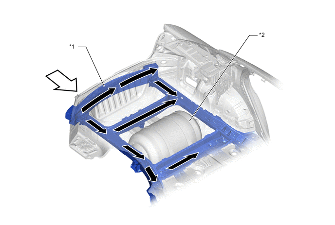
*1 Rear Bumper Reinforcement Sub-assembly *2 No. 2 Hydrogen Tank Assembly Impact Path to Collision Energy -
The fastening portions of the body and unit are composed of the steel frame rear crossmember sub-assemblies, and loading from road surface and side collisions is also shared and blocked by frame crossmembers made from CFRTP*, providing a design that suppresses deformation of the FC stack assembly.
-
In a side collision, the steel frame rear crossmember sub-assemblies are deformed, absorbing the bending load and suppressing folding deformation of the CFRTP frame crossmembers.
-
Shocks from the road surface are suppressed by the CFRTP-made frame crossmembers, suppressing deformation of the FC stack assembly.
Tech Tips
*: CFRTP: Carbon Fiber Reinforced Thermoplastics
*1 Rear Frame Assembly *2 Rear Body Support Bracket Reinforcement *3 Frame Rear Crossmember Extension *4 Frame Rear Crossmember Sub-assembly *5 FC Stack Assembly *6 FC Converter Assembly *7 Frame Center Crossmember Sub-assembly - - *a A-A Cross Section *b Deforms to absorb impact force *c Deformation is suppressed *d B-B Cross Section All connecting portions are linked circular steel frame construction Impact 
Force Input - -
-
-
Roof Crush Resistance
-
The collision energy from a collision with the roof is dispersed by the front body pillar outer reinforcement upper, center body pillar sub-assembly outer, and roof panel reinforcement in order to suppress deformation of the cabin.
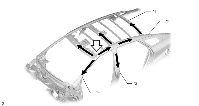
*1 Roof Panel Reinforcement *2 Roof Side Rail Reinforcement Outer *3 Center Body Pillar Sub-assembly Outer *4 Front Body Pillar Outer Reinforcement Upper
-
-
Other Occupant Protection Device
-
For cases in which the reaction from a collision causes the occupants' heads or other body parts to impact any of the pillars or the roof side portion, a head impact mitigation construction is employed which employs hollow spaces to absorb the energy of head impacts. The garnishes and roof headlining assembly, which have been molded with a ribbed construction that has a shock absorbing effect, contain internal energy absorbing pads, and in the case of impact, these are crushed in order to reduce the severity of impact forces applied to the heads of occupants.
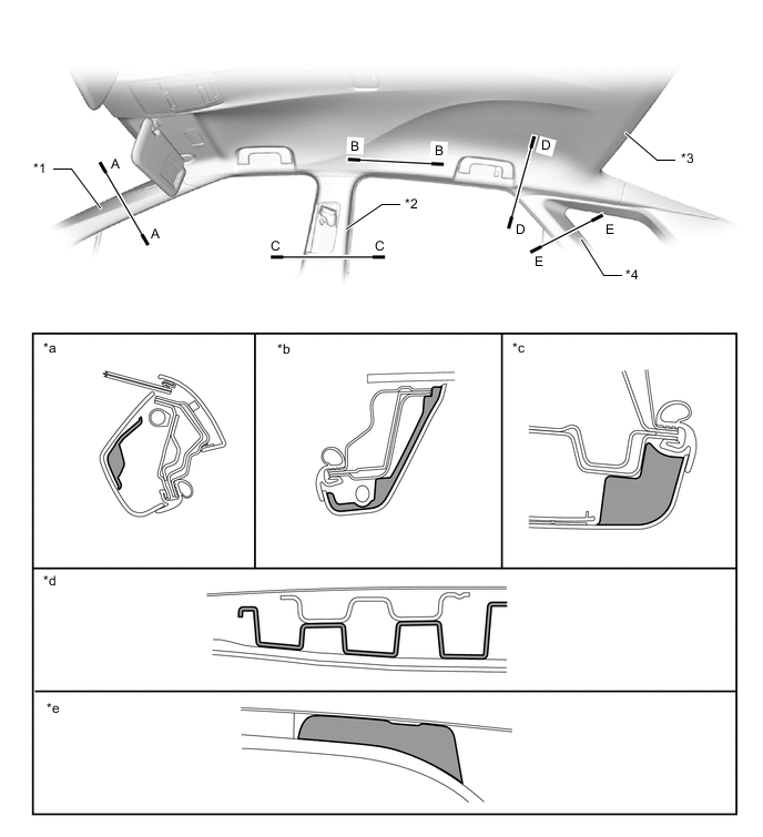
*1 Front Pillar Garnish *2 Center Pillar Garnish Assembly *3 Roof Headlining Assembly *4 Roof Side Inner Garnish Assembly *a A-A Cross Section *b E-E Cross Section *c C-C Cross Section *d B-B Cross Section *e D-D Cross Section - - 
Energy Absorbing Rib and Energy Absorbing Pad - - -
In order to reduce the severity of impacts to occupants' abdominal and lumbar regions in a side collision, the front door trim panel assembly and rear door trim panel assembly incorporate a crushable internal structure, and the front door trim pad and trim pad lower have been provided.
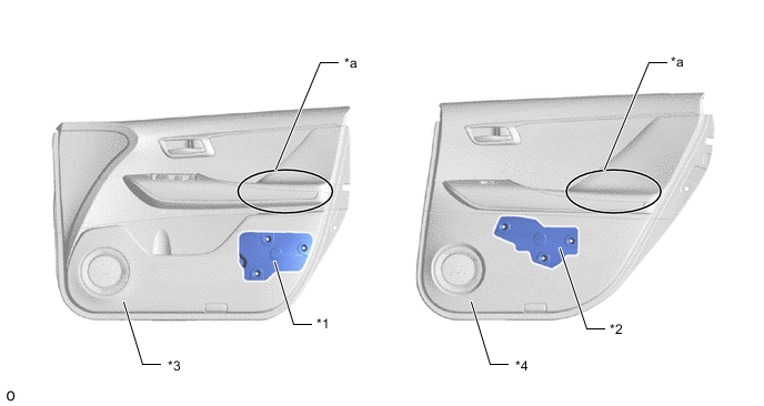
*1 Front Door Trim Pad *2 Rear Door Trim Pad *3 Front Door Trim Board Sub-assembly *4 Rear Door Trim Board Sub-assembly *a Crushable Internal Structure - -
-
-
Reduction Pedestrian Head Injury
-
In the event that the vehicle strikes a pedestrian, a pedestrian injury reduction body has been employed with the goal of reducing injury to the pedestrian. The hood sub-assembly, cowl top ventilator louver sub-assembly surroundings, front fender apron sub-assembly surroundings, and front bumper surroundings employ impact-absorbing construction in order to reduce the severity of impact forces applied to pedestrians' heads, legs, and other body parts.
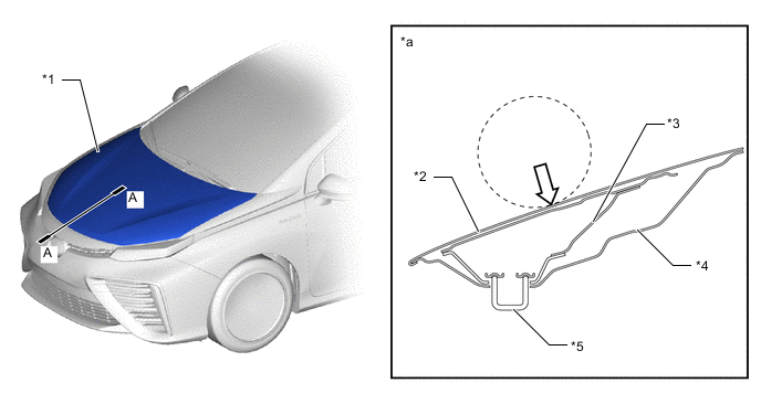
*1 Hood Sub-assembly *2 Hood Panel *3 Hood Panel Reinforcement *4 Hood Inner Panel *5 Hood Lock Hook Sub-assembly - - *a A-A Cross Section - - Impact - - -
The area around the cowl top ventilator louver sub-assembly employs a crushable design which offers a high level of energy absorption efficiency in the probably direction of head impact in order to reduce the severity of impact forces applied to pedestrians' heads. The cowl top ventilator louver sub-assembly employs an impact absorbing construction which, while maintaining the necessary level of stiffness, reduces the deformation strength in order to impacts. Also, the cowl top panel inner absorbs impacts by collapsing like a pantograph.
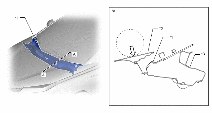
*1 Cowl Top Ventilator Louver Sub-assembly *2 Hood Sub-assembly *3 Cowl Top Panel Inner - - *a A-A Cross Section - - Impact - - -
The front bumper energy absorber in front of the front bumper reinforcement, and the plastic resin front bumper absorber lower beneath the radiator grille are provided to reduce the impact to pedestrians' lower extremities in the even of a collision.
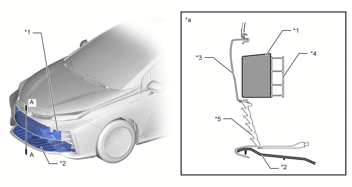
*1 Front Bumper Energy Absorber *2 Front Bumper Absorber Lower *3 Front Bumper Cover *4 Front Bumper Reinforcement *5 Radiator Grille Sub-assembly LWR - - *a A-A Cross Section - -
-
-