AIR CONDITIONING SYSTEM
-
CONSTRUCTION
-
An air conditioning unit that is compatible with left and right independent temperature control is used.
-
A partial recirculation structure that circulates a portion of the air in the cabin when in fresh air mode is used in an effort to improve heater performance.
-
A Revolutionary super-Slim structure (RS) type evaporator is used.
-
A Straight Flow Aluminum-II (SFA-II) heater core that is compact and offers advanced performance is used.
-
A compact wide-angle high flow defroster that gives the defroster nozzle assembly inner wall a radial shape is used to ensure superior defroster performance.
-
A pollen removal type filter is used.
-
The adoption of the rear heater duct and the console box duct improves comfort for the rear seat passengers.
Figure 1. Air Conditioning Unit Layout Parts Location
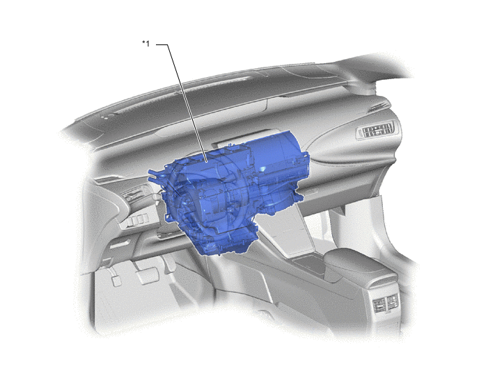
*1 Air Conditioning Unit Assembly - - Figure 2. Duct Layout Parts Location
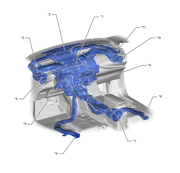
*1 Center Register Duct *2 Front Defroster Duct *3 Driver Side Defroster Duct *4 Driver Side Register Duct *5 Driver Side Footwell Register Duct *6 Driver Side Rear Footwell Register Duct *7 Console Box Duct No. 4 *8 Front Passenger Side Rear Footwell Register Duct *9 Front Passenger Side Footwell Register Duct *10 Front Passenger Side Register Duct *11 Front Passenger Side Defroster Duct - -
-
-
OPERATION
-
Mode Position and Damper Operation
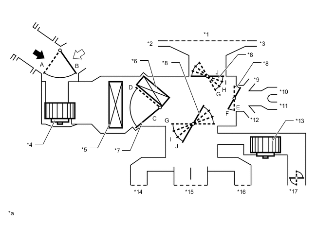
*1 Front Defroster *2 Driver Side Defroster *3 Front Passenger Side Defroster *4 Blower Motor with Fan Assembly *5 No. 1 Cooler Evaporator Sub-assembly *6 Air Conditioning Radiator Sub-assembly *7 Air Mix Control Door *8 Mode Switching Door *9 Front Passenger Side Footwell Register *10 Front Passenger Side Rear Footwell Register *11 Driver Side Rear Footwell Register *12 Driver Side Footwell Register *13 Cooler Blower Assembly *14 Driver Side Register *15 Center Register *16 Front Passenger Side Register *17 Console Box Duct No. 4 - - *a This illustration is a model diagram showing the damper positions in each mode. The parts layout and the number of the dampers in the illustration are different from those of the actual system. - - 
Fresh Air 
Recirculated Air Mode Position and Door Operation Control Door Operation Position Door Position Operation Air Inlet Control Door FRESH B Brings in fresh air. RECIRCULATION A Recirculates internal air. Air Mix Control Door HI - LO C - D Varies the mixture ratio of the hot air and the cool air in order to regulate the temperature continuously from HI to LO. Mode Control Door FACE E, J Air blows out of the front center register, side register. BI-LEVEL F, J Air blows out of the front center register, side register, console rear face register and front and rear footwell register ducts. FOOT F, I Air blows out of the front footwell register, rear footwell register and front register ducts. In addition, air blows out slightly from the front defroster. FOOT/DEF F, H Defrosts the windshield through the front defroster. At the same time, air is blown out from the footwell register, rear footwell register and the side register. DEF E, G Defrosts the windshield through the front defroster and side defroster. A small amount of air also blows out from the side register. -
Air Outlets and Airflow Volume (for All Seat Control Modes)
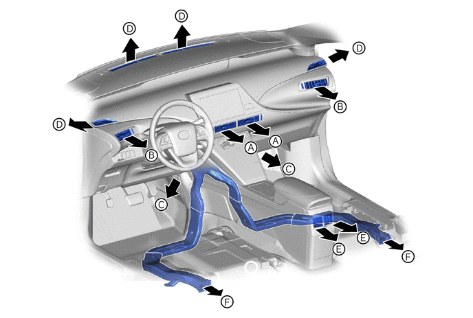
MODE A B C D E F Center Register Side Register Front Footwell Defroster Console Rear Face Register Rear Footwell 
FACE 
- - - 
BI-LEVEL 
- 
FOOT - 
- 
FOOT/DEF - - 
DEF - - - -
-