AIR CONDITIONING SYSTEM
-
CONSTRUCTION
-
Air conditioning related switches, blower outlets, temperature settings, etc. are indicated on a liquid crystal display inside the integration control and panel sub-assembly, located in the center of the instrument panel.
-
For some of the air conditioning control switches, electrostatic capacitance type switches have been adopted. The capacitive displacement when the switch is touched is detected, and the air conditioning system performs the relevant control.
-
A system with independent left and right temperature control has been adopted, and together with independent temperature setting switches on the driver and passenger sides, a DUAL switch that switches between independent left/right temperature control and linked control has been adopted.
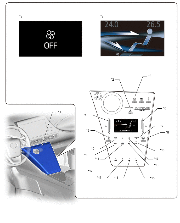
*1 Integration Control & Panel Assembly - - *2 Fresh/Recirculation Switch *3 ECO Drive Mode Switch *4 Temperature Setting Switch (Driver Side) *5 Front Defroster Switch *6 Temperature Setting Switch (Front Passenger Side) *7 Air Outlet Mode Switching Switch *8 Rear Window Defogger and Mirror Heater Switch *9 AUTO Switch *10 OFF Switch *11 ECO Air Conditioning Mode Switch *12 Seat Heater Switch (Driver Seat) *13 Steering Heater Switch *14 Deicer Switch *15 Seat Heater Switch (Front Passenger Seat) *16 A/C Switch *17 Blower Switch *18 DUAL Switch - - *a The illustration shown is an example only. The illustration may differ from the actual vehicle screen. - -
-