AIR CONDITIONING SYSTEM
-
FUNCTION OF MAIN COMPONENTS
-
The air conditioning system consists of the following parts:
Component Function Blower Motor with Fan Sub-assembly Controls the blower motor with fan sub-assembly in accordance with the airflow volume that has been calculated by the neural network control based on the input signals from various sensors. No. 1 Blower Damper Servo Sub-assembly Fresh/Recirculation Damper Driven by the air conditioning amplifier assembly to move the fresh/recirculation damper. Air Conditioning Radiator Damper Servo Sub-assembly No. 2 Driver Side Air Mix Controlled by the air conditioning amplifier assembly to move the driver seat air mix control damper and adjust the driver side outlet air temperature. Air Conditioning Radiator Damper Servo Sub-assembly No. 3 Passenger Side Air Mix Controlled by the air conditioning amplifier assembly to move the front passenger seat air mix control damper and adjust the front passenger side outlet air temperature. Air Conditioning Radiator Damper Servo Sub-assembly No. 1 Mode Switching Controlled by the air conditioning amplifier assembly to move the mode control damper and switch the registers. Air Conditioning Amplifier Assembly Transmits and receives data to and from the switches and sensors, and controls the air conditioning system. Integration Control & Panel Assembly Allows operation and adjustment of the air conditioning system via switches. FC Control ECU Sends data to and receives data from the air conditioning amplifier assembly via CAN communication. EV Control ECU Sends data to and receives data from the air conditioning amplifier assembly via CAN communication. Power Steering ECU Assembly Sends data to and receives data from the air conditioning amplifier assembly via CAN communication. 3 Way Valve (Heater Accessory Assembly) The valve is driven according to control by the air conditioning amplifier assembly and EV control ECU to change the open and closed locations in response to FC coolant temperature, which changes the FC coolant fluid path. Electric Heater Sub-Assembly Driven according to air conditioning amplifier assembly and EV control ECU control, and warms the coolant. Compressor with Motor Assembly Performs suction, compression and discharge of refrigerant gas. Cooler Blower Assembly Maneuvering the dial at the bottom of the rear seat blower outlet modulates the flow of cool air to the rear seats. No. 1 Cooler Thermistor Detects the temperature of the cool air past the cooler evaporator sub-assembly and transmits the data to the air conditioning amplifier assembly. Solar Sensor (Automatic Light Control Sensor) Detects the changes in the amount of solar energy and outputs them to the air conditioning amplifier assembly via the main body ECU (multiplex network body ECU). Room Temperature Sensor (Cooler Thermistor) Detects the internal temperature inside the cabin and outputs that data to the air conditioning amplifier assembly. Ambient Temperature Sensor (Thermistor Assembly) Detects ambient temperature and outputs it to the air conditioning amplifier assembly. Heater Water Pump Assembly Driven according to air conditioning amplifier assembly and EV control ECU control, and circulates the coolant. Air Conditioning Thermistor Assembly Detects the glass temperature, glass surroundings temperature and glass humidity, and outputs them to the air conditioning amplifier assembly. Air Conditioning Pressure Sensor Detects the refrigerant pressure and sends the data to the air conditioning amplifier assembly. PTC Heater (Quick Heater Assembly) Consists of a Positive Temperature Coefficient (PTC) element, an aluminum fin and a brass plate.
-
-
SYSTEM CONTROL
-
Control List
Control Function Neural Network Control This control is capable of performing complex control by artificially simulating the information processing method of the nervous system of living organisms in order to establish a complex input/output relationship that is similar to a human brain. Outlet Air Temperature Control Based on the temperature set by the temperature control switch, the neural network control calculates the outlet air temperature based on the input signals from various sensors. The temperature setting for the driver and front passenger is controlled independently in order to provide a separate vehicle interior temperature for the right and left sides of the vehicle. Thus, air conditioning control that accommodates occupant preferences has been achieved. Blower Control Controls the blower motor in accordance with the airflow volume that has been calculated by neural network control based on the input signals from various sensors. Automatically increases the blower level when the defroster is on. Air Outlet Control Automatically switches the air outlets in accordance with the outlet mode that has been calculated by neural network control based on the input signals from various sensors. In accordance with the engine coolant temperature, outside air temperature, amount of sunlight, required blower, outlet temperature and vehicle speed conditions, this control automatically switches the blower outlet to FOOT/DEF mode to prevent the windows from becoming fogged when the outside air temperature is low. Air Inlet Control Automatically controls the air inlet control damper to achieve the calculated outlet air temperature that is required. Drives the No. 1 blower damper servo sub-assembly (fresh/recirculation damper) in accordance with the operation of the air inlet control switch and moves the dampers to the FRESH or RECIRC position. Compressor Control The air conditioning amplifier assembly calculates the target speed of the compressor based on the target evaporator temperature (which is calculated by the room temperature sensor, ambient temperature sensor and solar sensor) and the actual evaporator temperature that is detected by the evaporator temperature sensor in order to control the compressor speed. Turns the air conditioning on automatically when the AUTO button is pressed when the blower is on and the air conditioning is OFF. Decreases the compressor speed in order to ensure quietness when the vehicle is stopped or the engine is off. PTC Heater Control When the power switch is turned on (IG) and the blower motor is turned on, the air conditioning amplifier assembly turns on the PTC heater (quick heater assembly) if the following conditions are met.
-
Engine coolant temperature is below the specified temperature.
-
Ambient temperature is below the specified temperature.
-
Tentative air mix damper opening angle is above the specified value (MAX HOT).
Rear Window Defogger Control
-
Switches the rear defogger and outside rear view mirror heaters on for 15 minutes when the rear defogger and mirror heater switch is pressed.
-
Switches them off if the button is pressed while they are operating.
Windshield Deicer Control Switches the windshield deicer on for approx. 15 minutes when the windshield deicer switch is pressed. Turns on when the hybrid system is started while the outside temperature is low, and turns off after approx. 15 minutes automatically. Outside Temperature Indication Control Based on the signals from the thermistor assembly, this control calculates the outside temperature, and this value is then corrected in the air conditioning amplifier, and shown on the multi-information display. ECO Drive Mode Control
-
When set to ECO air conditioning mode, the air conditioning amplifier assembly reduces the operation of the heater or the compressor with motor assembly, and at the same time reduces the blower speed.
-
Pressing the ECO air conditioning mode switch cancels the ECO air conditioning mode. Also, pressing and holding the switch changes to Eco air conditioning Hi mode.
Diagnosis A Diagnostic Trouble Code (DTC) is stored in memory when the air conditioning amplifier assembly detects a problem with the air conditioning system. -
-
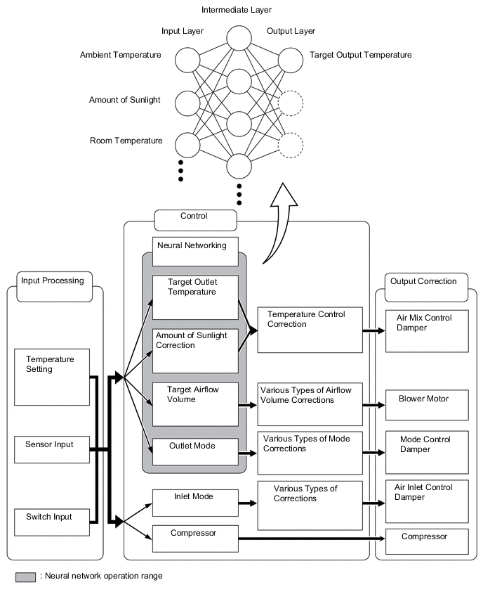
Neural Network Control
-
In the previous automatic air conditioning system, the air conditioning amplifier assembly determined the required outlet air temperature and blower air volume in accordance with a calculation formula that had been obtained based on information received from the sensors. However, because the senses of a person are rather complex, a given temperature is sensed differently, depending on the environment in which the person is situated. For example, a given amount of solar radiation can feel comfortably warm in a cold climate, but extremely uncomfortable in a hot climate. Therefore, as a technique for performing a high level of control, a neural network is used in the automatic air conditioning system. With this technique, the data that has been collected under varying environmental conditions is stored in the air conditioning amplifier assembly, which effects control to provide enhanced air conditioning comfort.
-
The neural network control consists of neurons in an input layer, an intermediate layer, and an output layer. The input layer neurons process the input data of the ambient temperature, the amount of sunlight and the room temperature based on the outputs of the switches and sensors, and output them to the intermediate layer neurons. Based on this data, the intermediate layer neurons adjust the strength of the links among the neurons. The sum of this data is then calculated by the output layer neurons in the form of the required outlet temperature, solar correction, target airflow volume and outlet mode control volume. Accordingly, the air conditioning amplifier assembly controls the servo motors and blower motor with fan sub-assembly in accordance with the control volumes that have been calculated by the neural network control.
-
-
ECO air conditioning mode control
-
In Eco air conditioning mode control, there are two types, the normal Eco air conditioning mode, and Eco air conditioning Hi mode, which gives fuel efficiency an even higher priority. Under specific conditions, the air conditioning amplifier assembly operates at a reduced level of air conditioning performance in order to improve fuel efficiency. Eco air conditioning mode can be selected by operating the Eco air conditioning switch.
Control Outline Inside/Outside Air Switch Control If the outside air temperature exceeds a certain limit, the mode switches to inside air recirculation. Blower Level Control In AUTO mode, the blower level is lowered to the specified value and control is performed. Also, when in warm-up control, the blower level decreases. Heater and Compressor Control The operation of the heater or the compressor with motor assembly is decreased, to a reserved operation level.
-
By pressing the Eco air conditioning mode switch, the air conditioning system can be turned on, but when the ECO drive mode switch in the integration control and panel assembly has been operated to set Eco drive mode, the air conditioning will also automatically enter Eco air conditioning mode control.
-
Pressing and holding the Eco air conditioning mode switch sets Eco air conditioning Hi mode, and air conditioning control will be performed with fuel efficiency as an even higher priority (air conditioning will have more reserved operation).
-
If DEF mode is selected, air conditioning related Eco air conditioning mode control will be cancelled in order to reduce fogging of the windows as quickly as possible. However, if DEF mode is cancelled, Eco air conditioning mode control will be restored.
-
Pressing the Eco air conditioning mode switch again will cancel the Eco air conditioning mode control.
-
-
-
Heat control
-
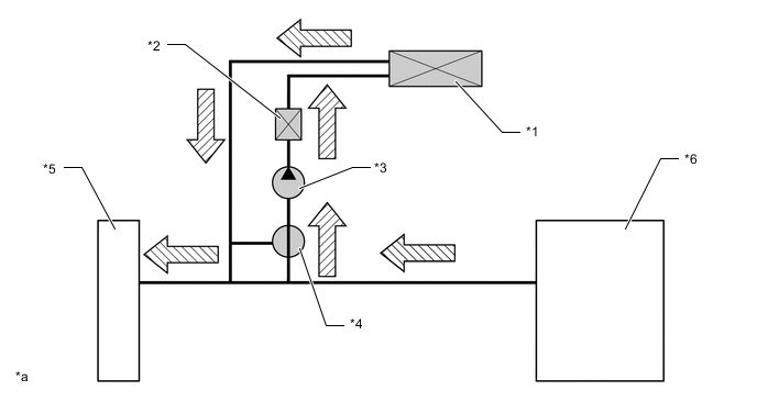
When the FC coolant temperature is low, the water heater (electric heater assembly) is used to raise the coolant temperature and pass it to the heater radiator unit sub-assembly.
-
When the FC coolant is at or higher than the specified temperature, the water heating electrical heater (electric heater assembly) is used together with the heat produced by the FC stack assembly during electrical generation, reducing the energy consumption of the heater while maintaining heating performance. At this time, the heater 3-way valve (heater accessory assembly) opens to the heater radiator unit sub-assembly side and the FC stack assembly side opens, the heat generated by the FC stack assembly is utilized, and passed to the circuit.
-
When the FC stack coolant temperature is high, such as when driving at high speed, the heater 3-way valve (heater accessory assembly) opens fully, and the FC coolant heat is taken up to the maximum extent possible by the water heater (electric heater assembly), the heating output of which stops upon reaching the specified temperature to improve fuel efficiency.
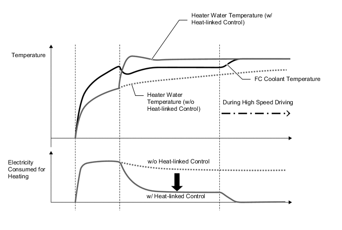
Figure 1. Coolant Flow (when FC Coolant Temperature is Low)
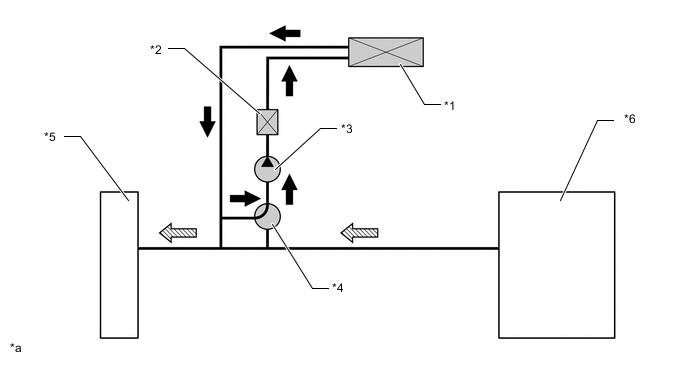
*1 Radiator Unit Sub-assembly *2 Electric Heater Sub-assembly *3 Heater Water Pump with Motor Assembly *4 3 Way Valve (Heater Accessory Assembly) *5 FC Radiator Assembly *6 FC Stack Assembly 
Heater Circuit Flow 
FC Coolant Flow *a The drawing is for illustrative purposes only. - - Figure 2. Coolant Flow (when FC Coolant Temperature is Medium)
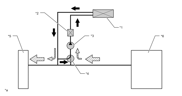
*1 Radiator Unit Sub-assembly *2 Electric Heater Sub-assembly *3 Heater Water Pump with Motor Assembly *4 3 Way Valve (Heater Accessory Assembly)
-
Radiator Unit Sub-assembly side: Open
-
FC Stack Assembly Side: Close
*5 FC Radiator Assembly *6 FC Stack Assembly Heater Circuit Flow FC Coolant Flow *a The drawing is for illustrative purposes only. - - Figure 3. Coolant Flow (when FC Coolant Temperature is High)
*1 Radiator Unit Sub-assembly *2 Electric Heater Sub-assembly *3 Heater Water Pump with Motor Assembly *4 3 Way Valve (Heater Accessory Assembly)
-
Radiator Unit Sub-assembly side: Close
-
FC Stack Assembly Side: Open
*5 FC Radiator Assembly *6 FC Stack Assembly FC Coolant Flow - - *a The drawing is for illustrative purposes only. - - -
-
-
-
DIAGNOSIS
-
The air conditioning amplifier assembly has a self-diagnosis function. It stores any operation malfunctions in the air conditioning system or heater system in memory in the form of Diagnostic Trouble Codes (DTCs). For details, refer to the Repair Manual.
-