PRE-CRASH SAFETY SYSTEM
-
FUNCTION OF MAIN COMPONENTS
Item Function Millimeter Wave Radar Sensor Assembly
-
Radiates millimeter radar waves forward, uses the reflected millimeter waves for detecting the presence of a vehicle ahead, the vehicle-to-vehicle distance, the relative speed and direction then transmits this information to the driving support ECU assembly.
-
Sounds the driving support buzzer (skid control buzzer) according to signals from the driving support ECU assembly.
Driving Support ECU Assembly Determines whether the possibility of a collision is high or a collision is unavoidable based on the information received from the millimeter wave radar sensor assembly. It then outputs a brake assist standby request signal and pre-crash brake request signal if required. Brake Booster with Master Cylinder Assembly Skid Control ECU
-
Receives a brake assist standby request signal from the driving support ECU assembly, and switches the brake assist to standby mode. When a stop light switch signal is input, it activates the brake assist.
-
Receives a pre-crash brake request signal from the driving support ECU assembly, and then applies the brakes.
-
Transmits vehicle speed signals to the driving support ECU assembly.
Brake Actuator Actuates the brakes in accordance with the signals from the skid control ECU. Brake Master Cylinder Pressure Sensor Detects the master cylinder pressure and transmits a signal to the skid control ECU. Brake Booster Pump Assembly Pump Motor Receives an operation signal from the skid control ECU and generates hydraulic pressure for brake control. Combination Meter Assembly PCS Warning Light
-
Flashes or illuminates to warn the driver in accordance with signals from the driving support ECU assembly.
-
Flashes when the system is malfunctioning.
-
Illuminates when the pre-crash safety system is not available due to certain reasons or when pre-crash brake and pre-crash brake assist operation are disabled using the VSC OFF switch.
Master Warning Light Illuminates to warn the driver in accordance with signals from the driving support ECU assembly. Multi-information Display Displays a warning message to inform or warn the driver of the system condition in accordance with signals from the driving support ECU assembly. Multi Buzzer Sounds to warn the driver in accordance with signals from the driving support ECU assembly when the system is malfunctioning. Airbag ECU Assembly Yaw Rate Sensor Detects the yaw rate of the vehicle and transmits the signal to the driving support ECU assembly. Deceleration Sensor Detects the longitudinal and lateral acceleration and deceleration of the vehicle and transmits the signal to the driving support ECU assembly. Spiral Cable with Sensor Sub-assembly Steering Sensor Detects the steering direction and angle of the steering wheel and transmits the signal to the driving support ECU assembly. Speed Sensor Detects the wheel speed of each of the 4 wheels and transmits the signals to the skid control ECU. Driving Support Buzzer (Skid Control Buzzer) Sounds to warn the driver in accordance with signals from the millimeter wave radar sensor assembly. Stop Light Switch Assembly
-
Detects the depressing of the brake pedal and transmits a signal to the skid control ECU.
-
Illuminates the stop lights in accordance with the signals from the skid control ECU.
Pre-crash System Cancel Switch Assembly By operating the switch, the pre-crash warning system can be turned ON/OFF, and the different warning timings can be switched between. Integration Control and Panel Assembly VSC OFF Switch Disables the pre-crash brake and pre-crash brake assist operation when the switch is turned on (VSC OFF mode). The PCS warning light turns on to show that the pre-crash brake and pre-crash brake assist operation is disabled. -
-
SYSTEM CONTROL
-
High Possibility of Collision or Unavoidable Collision
(1) The driving support ECU assembly determines that the possibility of a collision is high based on the signals received from the millimeter wave radar sensor assembly, steering sensor, speed sensor, deceleration sensor and yaw rate sensor. (2) The driving support ECU assembly transmits a PCS warning display request signal to the combination meter assembly and a driving support buzzer (skid control buzzer) request signal to the millimeter wave radar sensor assembly. (3) The driving support ECU assembly outputs a pre-crash brake assist request signal to the skid control ECU. Upon receiving this signal, the skid control ECU switches the brake assist to the standby condition. At this time, the skid control ECU activates pre-crash brake assist when the brake pedal is depressed by the driver. (4) The driving support ECU assembly determines that an unavoidable collision condition exists based on the signals received from the millimeter wave radar sensor assembly, steering sensor, speed sensor, deceleration sensor and yaw rate sensor. (5) The driving support ECU assembly outputs a pre-crash brake request signal to the skid control ECU. (6) The skid control ECU decreases the vehicle speed by activating the brake actuator to perform a pre-crash brake operation and illuminates the stop lights. (7) If no collision occurs, the brake assist will return to its normal state. 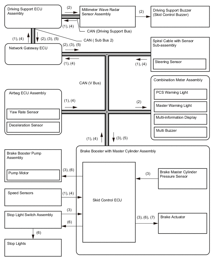
-
Operating Conditions
-
The pre-crash safety system operates when the driving support ECU assembly determines there is a high possibility of a collision or an unavoidable collision with an obstacle in front of the vehicle.
-
-
The following pre-crash safety system controls are performed under the following conditions.
Control Condition Pre-crash Warning
-
Pre-crash safety system operation has not been disabled using the pre-crash system cancel switch assembly.
-
Vehicle speed is approximately 15 km/h (10 mph) or above.
-
Relative speed of vehicle running ahead of you or obstacle is approximately 10 km/h (7 mph) or above.
Pre-crash Brake
-
Pre-crash safety system operation has not been disabled using the pre-crash system cancel switch assembly.
-
Vehicle speed is approximately 15 km/h (10 mph) or above.
-
Relative speed of vehicle running ahead of you or obstacle is approximately 10 km/h (7 mph) or above.
-
Not in VSC OFF mode.
Pre-crash Brake Assist
-
Pre-crash safety system operation has not been disabled using the pre-crash system cancel switch assembly.
-
Vehicle speed is approximately 30 km/h (19 mph) or above.
-
Relative speed of vehicle running ahead of you or obstacle is approximately 30 km/h (19 mph) or above.
-
Brake pedal is depressed.
-
Not in VSC OFF mode.
-
-
-
DIAGNOSIS
-
Initial Check
-
The driving support ECU assembly performs an initial check on the system for approximately 3 seconds after the power switch has been turned on (IG).
-
-
Monitor Function
-
After completing the initial check, the pre-crash safety system becomes ready to operate. During this time, the driving support ECU assembly periodically monitors the system for any malfunctions.
-
-
Diagnostic Trouble Code (DTC)
-
If the driving support ECU assembly detects a malfunction in the pre-crash safety system, it stores a 5 digit Diagnostic Trouble Code (DTC) in memory.
-
-