CAN COMMUNICATION SYSTEM
Figure 1. (LHD Model)
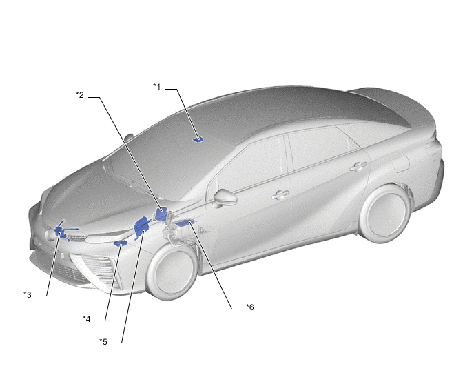
| *1 | Lane Departure Warning Camera | *2 | Brake Booster with Master Cylinder Assembly
|
| *3 | Millimeter Wave Radar Sensor Assembly | *4 | Headlight Light Control ECU Sub-assembly LH |
| *5 | FC Control ECU | *6 | FC Converter Assembly
|
Figure 2. (RHD Model)
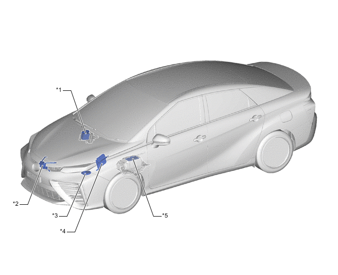
| *1 | Brake Booster with Master Cylinder Assembly
|
*2 | Millimeter Wave Radar Sensor Assembly |
| *3 | Headlight Light Control ECU Sub-assembly LH | *4 | FC Control ECU |
| *5 | FC Converter Assembly
|
- | - |
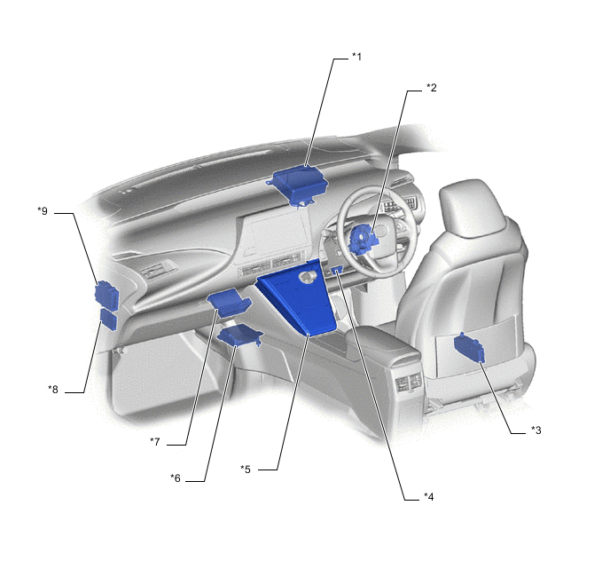
Figure 3. (LHD/RHD Model)
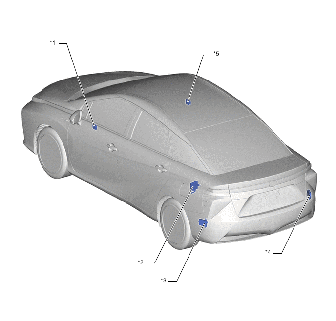
| *1 | Outer Mirror Control ECU Assembly LH | *2 | Hydrogen Fuel Control ECU Assembly |
| *3 | Blind Spot Monitor Sensor LH | *4 | Blind Spot Monitor Sensor RH |
| *5 | Outer Mirror Control ECU Assembly RH | - | - |
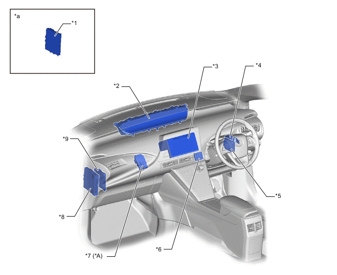
Figure 4. (LHD Model)
| *A | Models with Diagnosis Record ECU Assembly | - | - |
| *1 | Certification ECU (Smart Key ECU Assembly) | *2 | Combination Meter Assembly |
| *3 | EV Control ECU | *4 | Driving Support ECU Assembly |
| *5 | Clearance Warning ECU Assembly | *6 | Diagnosis Record ECU Assembly |
| *7 | Radio and Display Receiver Assembly | *8 | Multiplex Tilt and Telescopic ECU |
| *9 | Main Body ECU (Multiplex Network Body ECU) | - | - |
| *a | Refer to the Service Bulletin for the installation position of the parts. | - | - |
Figure 5. (RHD Model)
| *A | Models with Diagnosis Record ECU Assembly | - | - |
| *1 | Certification ECU (Smart Key ECU Assembly) | *2 | Combination Meter Assembly |
| *3 | Radio and Display Receiver Assembly | *4 | Clearance Warning ECU Assembly |
| *5 | Driving Support ECU Assembly | *6 | Multiplex Tilt and Telescopic ECU |
| *7 | Diagnosis Record ECU Assembly | *8 | EV Control ECU |
| *9 | Main Body ECU (Multiplex Network Body ECU) | - | - |
| *a | Refer to the Service Bulletin for the installation position of the parts. | - | - |
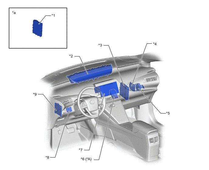
Figure 6. (LHD Model)
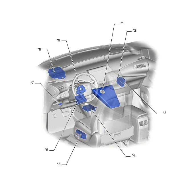
| *1 | Integration Control and Panel Assembly | *2 | Transmission Control ECU Assembly |
| *3 | Network Gateway ECU | *4 | Airbag ECU Assembly |
| *5 | Position Control ECU and Switch Assembly | *6 | Air Conditioning Amplifier Assembly |
| *7 | DLC3 | *8 | Power Steering ECU Assembly |
| *9 | Spiral Cable with Sensor Sub-assembly
|
- | - |
Figure 7. (RHD Model)
| *1 | Power Steering ECU Assembly | *2 | Spiral Cable with Sensor Sub-assembly
|
| *3 | Position Control ECU and Switch Assembly | *4 | DLC3 |
| *5 | Integration Control and Panel Assembly | *6 | Airbag ECU Assembly |
| *7 | Air Conditioning Amplifier Assembly | *8 | Network Gateway ECU |
| *9 | Transmission Control ECU Assembly | - | - |