REAR SUSPENSION SYSTEM
-
OUTLINE
-
A torsion-beam type suspension is used.
-
The rear axle carrier bushes are obliquely mounted to obtain a toe-correction function, thus providing excellent driving stability and ride comfort.
-
A rear axle beam dynamic damper was employed, reducing noise and vibration transmitted from the road surface when the vehicle is being driven, thus realizing a superior riding quality.
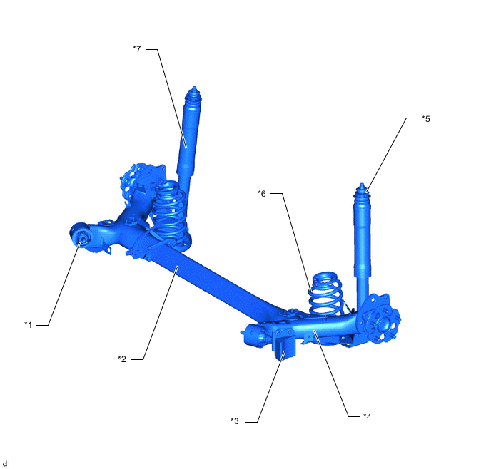
*1 Rear Axle Carrier Bush *2 Axle Beam (Rear Axle Beam Assembly) *3 Rear Axle Beam Dynamic Damper *4 Trailing Arm (Rear Axle Beam Assembly) *5 Rear Suspension Support *6 Rear Coil Spring *7 Rear Shock Absorber Assembly - -
-
-
MAIN FEATURES
-
Toe and Camber Change
-
In a torsion-beam type suspension, the camber angle and the toe change differ between bound and rebound cases, offering both straight-line stability and excellent cornering stability.
-
The same as a full-trailing arm type suspension, the axis that joins the center of the right and left bushings in the trailing arms is the center of movement during any same direction travel.
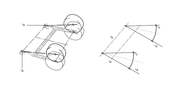
*a Center of Bushing *b Trailing Arm Center Line *c Bound *d Rebound *e Axle Beam Center Line - - -
When one side of the suspension compresses while the other side extends, or if any difference in the suspension travel is created between the right and left wheels, the axle beam twists with its shear center as the center of its rotation. Also, the camber change rate in relation to the suspension travel is determined by the ratio of the distance between the bushing in the trailing arm and the shear center ("α" in the figure below) and distance between the bushing in the trailing arm and the axle center ("L" in the figure below). Consequently, through the optimal configuration of the axle beam, the changes in the camber angle in relation to the suspension travel is optimized, thus ensuring excellent cornering performance.
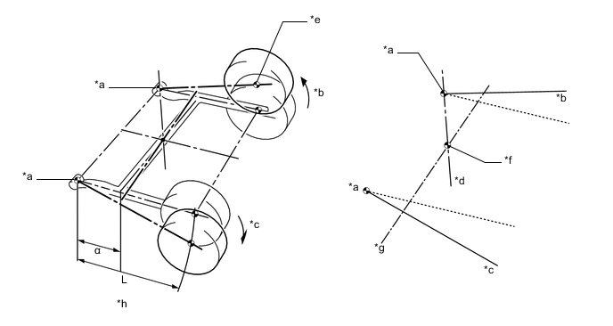
*a Center of Bushing *b Bound *c Rebound *d Instantaneous Rotational Axis of Right Axle *e Rear Axle Center *f Shearing Center *g Axle Beam Twist Center Line *h Camber Change Rate α/L
-
-
Toe-correction Function
-
The longitudinal and lateral forces that are created by the vehicle during cornering cause the bushings in the trailing arms to deform. In a right turn, the right trailing arm moves forward and the left trailing arm moves rearward, creating a tendency for the left wheel to toe out. In this situation, the bushings that are installed in the trailing arms of a vehicle with a toe-correction function are designed to utilize the lateral force, which is applied to the bushings during cornering, to correct the left trailing arm towards the toe-in direction.
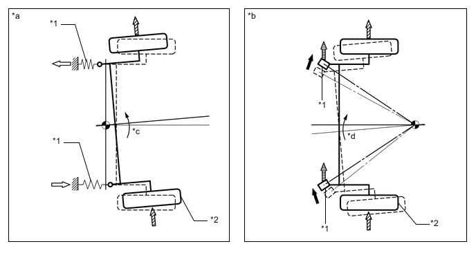
*1 Rear Torsion Beam Bush *2 Left Wheel *a Without Toe-correction Function *b With Toe-correction Function *c Toe-out *d Toe-in 
Bushing Movement 
Longitudinal Force 
Lateral Force 
Lateral Force Applied to the Bushing
-
-
Anti-lift Geometry
-
Lifting of the rear end of the vehicle during braking occurs due to the shifting of the center of gravity caused by inertia. The intersecting point (OR) supports the braking force (BF), and generates a force (BF1) in the direction of the intersecting point (OR) and a component force(BF2) in the direction of the ground contact. The force (BF1) can change the height of the intersecting point (OR). When the intersecting point (OR) is set high, it acts in the opposite direction (-▲W) of the load fluctuation (▲W) in order to restrain the lift.
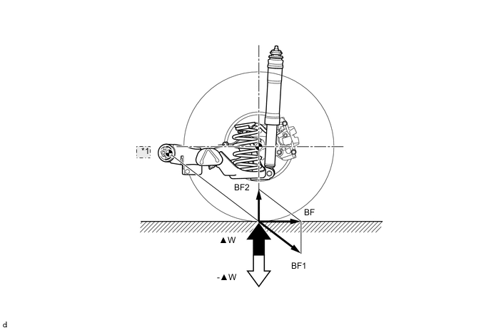
*1 OR
-
-