ELECTRONIC SHIFT LEVER SYSTEM
-
FUNCTION OF MAIN COMPONENTS
-
The main components of the electronic shift lever system have the following functions:
Component Function EV Control ECU
-
Performs shift control according to each shift position based on signals from shift lever position sensor, P position switch and various ECUs.
-
Sends parking lock/unlock request signals to the transmission control ECU assembly (P control function).
Transmission Control ECU Assembly
-
Drives the parking lock actuator (shift control actuator assembly) according to parking lock/unlock request signals from the EV control ECU.
Shift Lever (Transmission Instrument Panel Shift Assembly)
-
Shift Sensor
-
Select Sensor
-
Detects the shift lever operation to R, N and D positions and Br mode, and sends output to the EV control ECU.
Integration Control and Panel Assembly P Position Switch
-
Outputs P position switch operation signals to the EV control ECU.
P Position Indicator Light
-
Indicates the lock/unlock status of the parking lock mechanism.
Parking Lock Actuator (Shift Control Actuator Assembly)
-
Locks and unlocks the parking lock mechanism.
Parking Lock Actuator Relay(P COM MTR Relay)
-
Relay turns ON when power is supplied by transmission control ECU assembly (P control function), and provides power to the motor in the parking lock actuator (shift control actuator assembly).
Combination Meter Assembly
-
Indicates shift position using shift position indicator.
-
Sounds a buzzer continuously to warn the driver if the accelerator pedal is depressed while the shift position is in N during READY ON.
-
Sounds a buzzer and blinks the master warning light to warn the driver when the reject function has activated.
-
Sounds a buzzer illuminates the master warning light to warn the driver when the system is malfunctioning.
-
Displays a warning message to warn the driver when the system is malfunctioning or the reject function has activated.
-
-
-
SYSTEM CONTROL
-
Based on the shift position signal (R/N/D/Br mode) from the shift lever position sensor (transmission instrument panel shift assembly) and the P position signal from the P position switch (integration control and panel assembly), the EV control ECU performs control of driving using the FC system depending on each shift position, and at the same time sends parking lock/unlock request signals to the transmission control ECU assembly (P control function).
-
Based on the parking lock/unlock request signals from the EV control ECU, the transmission control ECU assembly (P control function) drives the parking lock actuator (shift control actuator assembly) to switch the parking lock mechanism between locked and unlocked. Also, the transmission control ECU assembly (P control function) sends parking lock status signals to the EV control ECU.
-
When the shift lever is operated to Br mode, the regenerative brakes or hydraulic brakes are activated to generate a level of deceleration equivalent to engine braking.
-
-
FUNCTION
-
Shift position shifting function
-
To enable the driver to operate the system at will and with a sense of security, the EV control ECU makes a comprehensive judgment of the vehicle conditions and then shifts the shift position.
-
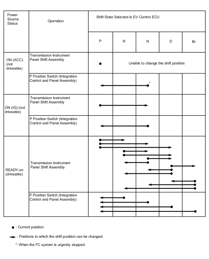
During normal driving, excluding the operating conditions for the reject function, all shift positions can be shifted to.
-
A function has been provided so that when the vehicle is stopped and the power switch is pushed to turn the power off, if the shift position is not in the P position, the system will automatically shift to the P position and then turn the power off.
-
-
Reject Function
-
To maintain safety, a reject function has been provided so that the shift position is not shifted when an incorrect shift lever operation is performed.
-
When the reject function operates, the shift position is maintained in P or N, or the position is shifted to N, and the buzzer (2 consecutive tones) in the combination meter assembly sounds and the master warning light blinks. Also, a warning message and handling method are displayed in the multi information display to warn the driver.
Reject Function Operating Conditions and Message Display Shift Operation Causing Reject Function to Operate Shift Position After Reject Function Operation Message in Multi-information Display Shift operated when auxiliary battery voltage is low Stays in P position Insufficient Aux Battery Charge Shift is Unavailable See Owner's Manual Shift lever selected to D or R while READY indicator is blinking Stays in P position Shifting Unavailable When READY Indicator is Flashing While consecutive operations are prohibited, shift lever is selected from P to a different position Stays in P position Shifting Temporarily Unavailable Wait a Moment and Try Again Shift lever selected from R position to Br mode N position Shifted to [N] Position Shift to [D] once, then Shift to [Br] Shift lever selected to D or R while ON (IG ON) and READY indicator is not illuminated Stays in P position Shifting to [D] or [R] Position Unavailable Try to Shift after FC System has Started Shift lever selected from P to a different position without depressing the brake pedal Stays in P position Shifting Unavailable Press Brake Pedal before Shifting Shift lever selected from P or N position to Br mode Stays in same position as before shifting operation (P or N) Shifting to [Br] Mode Unavailable Shift to [D] once, then Shift to [Br] Shift lever selected from R position to Bs mode N position Shifted to [N] Position Shift to [D] once, then Shift to [Br] Shift lever selected to R while vehicle is being driven forward* N position Shifted to [N] Position Stop Your Vehicle before Shifting to [R] Shift lever selected to D while vehicle is being driven in reverse* N position Shifted to [N] Position Stop Your Vehicle before Shifting to [D] Shift lever selected to P while vehicle is being driven N position Shifted to [N] Position To Shift to [P], Stop Your Vehicle and Press [P] Switch *: When the vehicle speed is 11 km/h or more
-
-
Shift position indicator display
-
The current shift position and the positions that can currently be shifted to are displayed by the shift position indicator in the combination meter assembly.
-
While driving in the D position, when a change to Br mode using the shift lever is confirmed, the Br mode indicator illuminates.
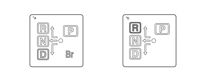
*a Display when in Br Mode *b Display when in R Position
-
-
Shift-related component malfunction display
-
When there is a malfunction in a shift-related component, the buzzer (single tone) in the combination meter assembly sounds and the master warning light illuminates.
Shift-related component malfunction message display Reason for Display Message on Multi-information Display The auxiliary battery voltage has decreased, and there is a possibility the parking lock mechanism cannot change to locked condition. Insufficient Aux Battery Charge When Parking, Apply Parking Brake Securely then See Owner's Manual Due to a malfunction in the shift system, there is a possibility the parking lock mechanism cannot change to locked condition. Shift System Malfunction When Parking, Apply Parking Brake Securely then See Owner's Manual A malfunction has occurred in the shift system. Shift System Malfunction See Owner's Manual An internal malfunction has occurred in the transmission control ECU assembly (P control function), and there is a possibility the parking lock mechanism cannot change to unlocked condition. Shift System Malfunction Shifting Unavailable See Owner's Manual A malfunction has occurred in a shift system sensor, and the shift position may not shift according the operations performed by the driver. Shift System Malfunction Stop Your Vehicle in a Safe Place then See Owner's Manual The P position switch (transmission shift main switch) is malfunctioning, and there is a possibility the parking lock mechanism cannot change to locked condition. [P] Switch Malfunction When Parking, Apply Parking Brake Securely then See Owner's Manual Communication inside the EV control ECU cannot be performed correctly, and there is a possibility the parking lock mechanism cannot change to locked condition. Shift System Malfunction When Parking, Apply Parking Brake Securely then See Owner's Manual
-
-
-
FAIL-SAFE
-
When a malfunction has occurred in the system, the fail safe function operates. When this happens, the master warning light in the combination meter assembly illuminates, a buzzer sounds, and a malfunction warning message is displayed in the multi-information display to inform the driver of the malfunction.
-
-
DIAGNOSIS
-
To make system inspection easier, a diagnosis function is employed. For information about the diagnosis method and diagnosis items, refer to the repair manual.
-