BRAKE CONTROL SYSTEM
-
CONSTRUCTION
-
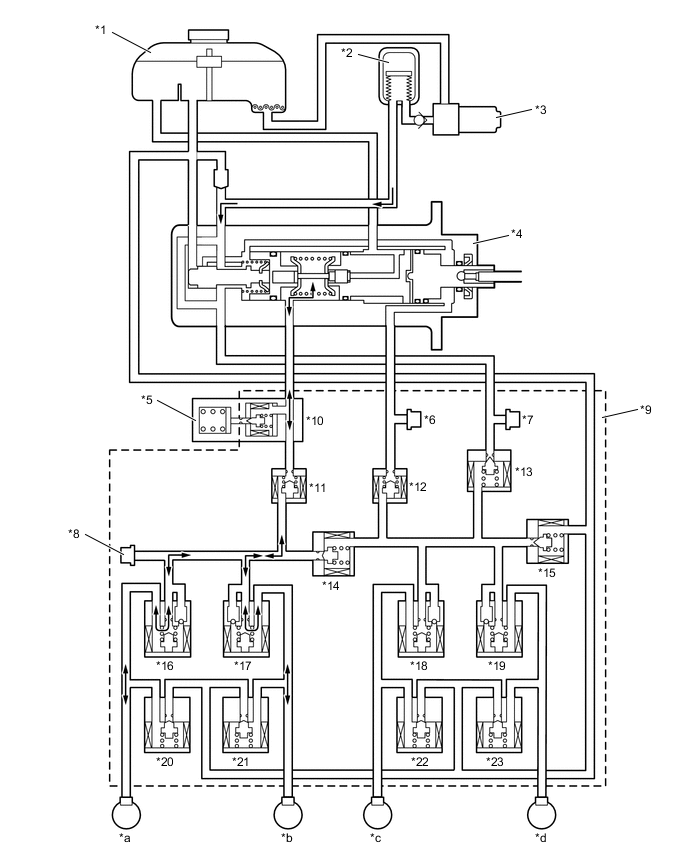
The brake actuator consists of the linear solenoid valves, switching solenoid valves, control solenoid valves, regulator pressure sensor, wheel cylinder pressure sensor and accumulator pressure sensor.
-
The brake actuator regulates the hydraulic brake pressure to each wheel cylinder.
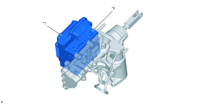
*1 Skid Control ECU *2 Brake Actuator -
The construction of the brake actuator, and the function of each component, is as follows:
Component Function Linear Solenoid Valve Controls the wheel cylinder pressure to generate a braking force responsive to the braking force requirement when the brake pedal is depressed normally. Switching Solenoid Valve Switches the brake hydraulic path when the brake control system is activated. Control Solenoid Valve
-
Pressure Holding Solenoid Valve
-
Pressure Reduction Solenoid Valve
Controls the wheel cylinder pressure when the ABS, EBD, brake assist, TRC, VSC and hill-start assist control are activated. Regulator Pressure Sensor The regulator pressure sensor converts the fluid pressure generated by the hydraulic brake booster into electrical signals and transmits them to the skid control ECU. Accordingly, the skid control ECU determines the braking force required by the driver. Wheel Cylinder Pressure Sensor This sensor detects the fluid pressure that acts on the respective wheel cylinders and transmits them to the skid control ECU in the form of feedback. Accordingly, the skid control ECU monitors the fluid pressure of the wheel cylinders and controls the control solenoid valve, in order to achieve the optimal wheel cylinder pressures. Accumulator Pressure Sensor The accumulator pressure sensor constantly detects the brake fluid pressure in the accumulator and transmits the signals to the skid control ECU. Accordingly, the skid control ECU controls the pump motor. 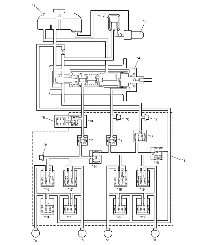
*1 Brake Master Cylinder Reservoir Assembly *2 Accumulator *3 Pump Motor *4 Brake Master Cylinder *5 Brake Master Stroke Simulator Cylinder Assembly *6 Regulator Pressure Sensor *7 Accumulator Pressure Sensor *8 Wheel Cylinder Pressure Sensor *9 Brake Actuator *10 Switching Solenoid Valve SSC *11 Switching Solenoid Valve SMC *12 Switching Solenoid Valve SRC *13 Linear Solenoid Valve SLA *14 Switching Solenoid Valve SCC *15 Linear Solenoid Valve SLR *16 Pressure Holding Solenoid Valve FLH *17 Pressure Holding Solenoid Valve FRH *18 Pressure Holding Solenoid Valve RLH *19 Pressure Holding Solenoid Valve RRH *20 Pressure Reduction Solenoid Valve FLR *21 Pressure Reduction Solenoid Valve FRR *22 Pressure Reduction Solenoid Valve RLR *23 Pressure Reduction Solenoid Valve RRR - - *a Front Brake LH *b Front Brake RH *c Rear Brake LH *d Rear Brake RH -
-
-
OPERATION
-
Normal Brake Operation (with Regenerative Brake Cooperative Control)
-
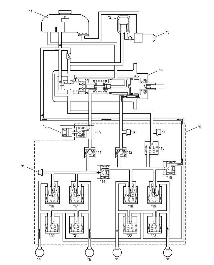
During normal braking, the switching solenoid valves SSC and SCC open and the switching solenoid valves SMC and SRC close, individually separating the fluid pressure circuit from the hydraulic brake booster to each wheel cylinder. Each of the wheel cylinder pressures can be increased, retained and decreased by controlling the linear solenoid valves SLA and SLR.
-
The skid control ECU calculates the braking force required by the driver in accordance with the signals received from the regulator pressure sensor and the brake pedal stroke sensor assembly. Then, the skid control ECU calculates the regenerative brake force value out of the required brake force and transmits the calculated value to the EV control ECU. Upon receiving the value, the EV control ECU generates a regenerative brake force. At the same time, the EV control ECU transmits the actual regenerative brake force value to the skid control ECU. The skid control ECU controls the solenoid valves in order to cause the hydraulic brake system to generate a brake force value (which is obtained by subtracting the regenerative brake force from the brake force value required by the driver).
-
The skid control ECU calculates the target wheel cylinder pressure (equivalent to the brake force required by the driver) in accordance with the signals received from the regulator pressure sensor and the brake pedal stroke sensor assembly. The skid control ECU compares the wheel cylinder pressure with the target wheel cylinder pressure. If the wheel cylinder pressure is lower than the target wheel cylinder pressure, the skid control ECU boosts the pressure in the brake actuator. Accordingly, the fluid pressure in the accumulator is fed into the wheel cylinder. Moreover, this operation is the same when the hydraulic brake force must be increased in order to effect cooperative control in accordance with the changes in the regenerative brake force.
*1 Brake Master Cylinder Reservoir Assembly *2 Accumulator *3 Pump Motor *4 Brake Master Cylinder *5 Brake Master Stroke Simulator Cylinder Assembly *6 Regulator Pressure Sensor *7 Accumulator Pressure Sensor *8 Wheel Cylinder Pressure Sensor *9 Brake Actuator *10 Switching Solenoid Valve SSC *11 Switching Solenoid Valve SMC *12 Switching Solenoid Valve SRC *13 Linear Solenoid Valve SLA *14 Switching Solenoid Valve SCC *15 Linear Solenoid Valve SLR *16 Pressure Holding Solenoid Valve FLH *17 Pressure Holding Solenoid Valve FRH *18 Pressure Holding Solenoid Valve RLH *19 Pressure Holding Solenoid Valve RRH *20 Pressure Reduction Solenoid Valve FLR *21 Pressure Reduction Solenoid Valve FRR *22 Pressure Reduction Solenoid Valve RLR *23 Pressure Reduction Solenoid Valve RRR - - *a Front Brake LH *b Front Brake RH *c Rear Brake LH *d Rear Brake RH Item Normal Braking Increase Mode Linear Solenoid Valve SLA On (Half-open*) SLR Off (Closed) Switching Solenoid Valve SSC On (Open) SCC On (Open) SMC On (Closed) SRC On (Closed) Pressure Holding Solenoid Valve FLH Off (Open) FRH Off (Open) RLH Off (Open) RRH Off (Open) Pressure Reduction Solenoid Valve FLR Off (Closed) FRR Off (Closed) RLR Off (Closed) RRR Off (Closed) Tech Tips
*: The solenoid valve constantly regulates the amount of opening of the valve in accordance with the use conditions in order to control the fluid pressure.
-
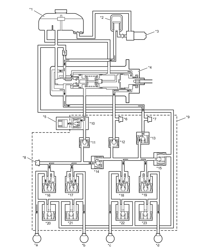
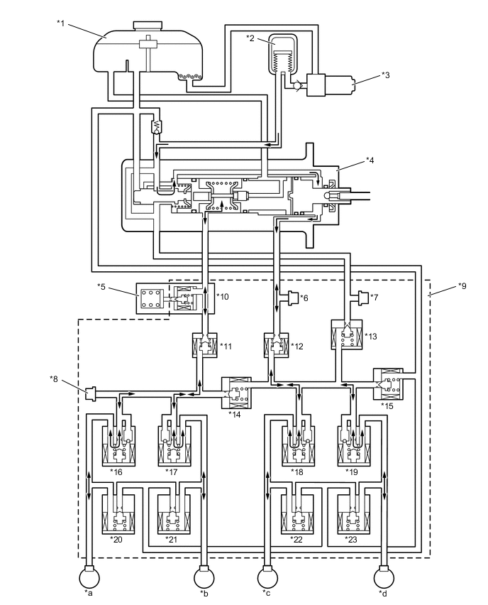
The skid control ECU calculates the target wheel cylinder pressure (equivalent to the brake force required by the driver) in accordance with the signals received from the regulator pressure sensor and the brake pedal stroke sensor assembly. The skid control ECU compares the wheel cylinder pressure with the target wheel cylinder pressure. If they are equal, the skid control ECU controls the brake actuator in the hold state. Accordingly, the wheel cylinders will be held at a constant pressure.
*1 Brake Master Cylinder Reservoir Assembly *2 Accumulator *3 Pump Motor *4 Brake Master Cylinder *5 Brake Master Stroke Simulator Cylinder Assembly *6 Regulator Pressure Sensor *7 Accumulator Pressure Sensor *8 Wheel Cylinder Pressure Sensor *9 Brake Actuator *10 Switching Solenoid Valve SSC *11 Switching Solenoid Valve SMC *12 Switching Solenoid Valve SRC *13 Linear Solenoid Valve SLA *14 Switching Solenoid Valve SCC *15 Linear Solenoid Valve SLR *16 Pressure Holding Solenoid Valve FLH *17 Pressure Holding Solenoid Valve FRH *18 Pressure Holding Solenoid Valve RLH *19 Pressure Holding Solenoid Valve RRH *20 Pressure Reduction Solenoid Valve FLR *21 Pressure Reduction Solenoid Valve FRR *22 Pressure Reduction Solenoid Valve RLR *23 Pressure Reduction Solenoid Valve RRR - - *a Front Brake LH *b Front Brake RH *c Rear Brake LH *d Rear Brake RH Item Normal Braking Holding Mode Linear Solenoid Valve SLA Off (Closed) SLR Off (Closed) Switching Solenoid Valve SSC On (Open) SCC On (Open) SMC On (Closed) SRC On (Closed) Pressure Holding Solenoid Valve FLH Off (Open) FRH Off (Open) RLH Off (Open) RRH Off (Open) Pressure Reduction Solenoid Valve FLR Off (Closed) FRR Off (Closed) RLR Off (Closed) RRR Off (Closed) -
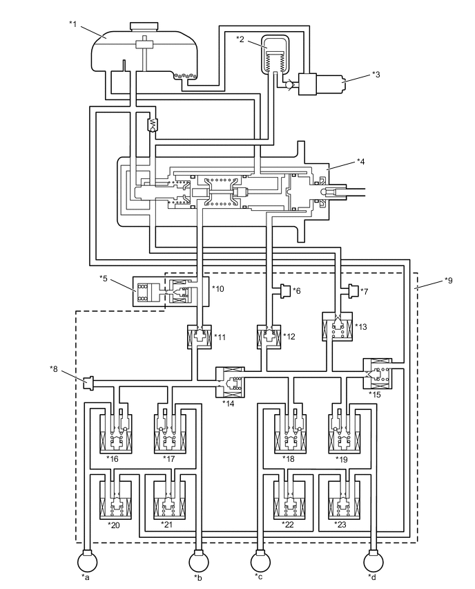
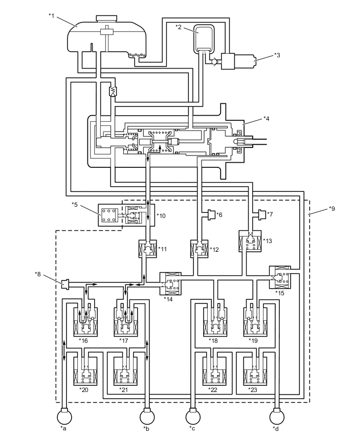
The skid control ECU calculates the target wheel cylinder pressure (equivalent to the brake force required by the driver) in accordance with the signals received from the regulator pressure sensor and the brake pedal stroke sensor assembly. The skid control ECU compares the wheel cylinder pressure with the target wheel cylinder pressure. If the wheel cylinder pressure is higher than the target wheel cylinder pressure, the skid control ECU reduces the pressure in the brake actuator. Accordingly, the pressure in the wheel cylinder decreases. Moreover, this operation is the same when the hydraulic brake force must be decreased in order to effect cooperative control in accordance with the changes in the regenerative brake force.
*1 Brake Master Cylinder Reservoir Assembly *2 Accumulator *3 Pump Motor *4 Brake Master Cylinder *5 Brake Master Stroke Simulator Cylinder Assembly *6 Regulator Pressure Sensor *7 Accumulator Pressure Sensor *8 Wheel Cylinder Pressure Sensor *9 Brake Actuator *10 Switching Solenoid Valve SSC *11 Switching Solenoid Valve SMC *12 Switching Solenoid Valve SRC *13 Linear Solenoid Valve SLA *14 Switching Solenoid Valve SCC *15 Linear Solenoid Valve SLR *16 Pressure Holding Solenoid Valve FLH *17 Pressure Holding Solenoid Valve FRH *18 Pressure Holding Solenoid Valve RLH *19 Pressure Holding Solenoid Valve RRH *20 Pressure Reduction Solenoid Valve FLR *21 Pressure Reduction Solenoid Valve FRR *22 Pressure Reduction Solenoid Valve RLR *23 Pressure Reduction Solenoid Valve RRR - - *a Front Brake LH *b Front Brake RH *c Rear Brake LH *d Rear Brake RH Item Normal Braking Reduction Mode Linear Solenoid Valve SLA Off (Closed) SLR On (Half-open*) Switching Solenoid Valve SSC On (Open) SCC On (Open) SMC On (Closed) SRC On (Closed) Pressure Holding Solenoid Valve FLH Off (Open) FRH Off (Open) RLH Off (Open) RRH Off (Open) Pressure Reduction Solenoid Valve FLR Off (Closed) FRR Off (Closed) RLR Off (Closed) RRR Off (Closed) Tech Tips
*: The solenoid valve constantly regulates the amount of opening of the valve in accordance with the use conditions in order to control the fluid pressure.
-
-
Fail-safe Operation
-
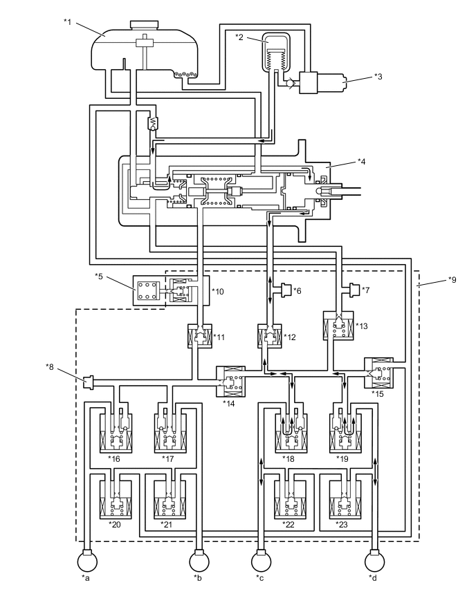
When the brake actuator stops, the switching solenoid valves SSC and SCC close and the switching solenoid valves SMC and SRC open. Thus, the fluid pressure generated in the brake master cylinder by the driver's brake pedal operation is directly supplied to each of the wheel cylinders.
*1 Brake Master Cylinder Reservoir Assembly *2 Accumulator *3 Pump Motor *4 Brake Master Cylinder *5 Brake Master Stroke Simulator Cylinder Assembly *6 Regulator Pressure Sensor *7 Accumulator Pressure Sensor *8 Wheel Cylinder Pressure Sensor *9 Brake Actuator *10 Switching Solenoid Valve SSC *11 Switching Solenoid Valve SMC *12 Switching Solenoid Valve SRC *13 Linear Solenoid Valve SLA *14 Switching Solenoid Valve SCC *15 Linear Solenoid Valve SLR *16 Pressure Holding Solenoid Valve FLH *17 Pressure Holding Solenoid Valve FRH *18 Pressure Holding Solenoid Valve RLH *19 Pressure Holding Solenoid Valve RRH *20 Pressure Reduction Solenoid Valve FLR *21 Pressure Reduction Solenoid Valve FRR *22 Pressure Reduction Solenoid Valve RLR *23 Pressure Reduction Solenoid Valve RRR - - *a Front Brake LH *b Front Brake RH *c Rear Brake LH *d Rear Brake RH Item System Off Linear Solenoid Valve SLA Off (Closed) SLR Off (Closed) Switching Solenoid Valve SSC Off (Closed) SCC Off (Closed) SMC Off (Open) SRC Off (Open) Pressure Holding Solenoid Valve FLH Off (Open) FRH Off (Open) RLH Off (Open) RRH Off (Open) Pressure Reduction Solenoid Valve FLR Off (Closed) FRR Off (Closed) RLR Off (Closed) RRR Off (Closed) -
When the accumulator pressure is not supplied due to a failure in the brake system, the skid control ECU closes the switching solenoid valves SSC and SCC and opens the switching solenoid valves SMC and SRC. At this time, the fluid pressure generated in the brake master cylinder is supplied only to the front wheel cylinders.
*1 Brake Master Cylinder Reservoir Assembly *2 Accumulator *3 Pump Motor *4 Brake Master Cylinder *5 Brake Master Stroke Simulator Cylinder Assembly *6 Regulator Pressure Sensor *7 Accumulator Pressure Sensor *8 Wheel Cylinder Pressure Sensor *9 Brake Actuator *10 Switching Solenoid Valve SSC *11 Switching Solenoid Valve SMC *12 Switching Solenoid Valve SRC *13 Linear Solenoid Valve SLA *14 Switching Solenoid Valve SCC *15 Linear Solenoid Valve SLR *16 Pressure Holding Solenoid Valve FLH *17 Pressure Holding Solenoid Valve FRH *18 Pressure Holding Solenoid Valve RLH *19 Pressure Holding Solenoid Valve RRH *20 Pressure Reduction Solenoid Valve FLR *21 Pressure Reduction Solenoid Valve FRR *22 Pressure Reduction Solenoid Valve RLR *23 Pressure Reduction Solenoid Valve RRR - - *a Front Brake LH *b Front Brake RH *c Rear Brake LH *d Rear Brake RH Item Power Supply Malfunction Linear Solenoid Valve SLA Off (Closed) SLR Off (Closed) Switching Solenoid Valve SSC Off (Closed) SCC Off (Closed) SMC Off (Open) SRC Off (Open) Pressure Holding Solenoid Valve FLH Off (Open) FRH Off (Open) RLH Off (Open) RRH Off (Open) Pressure Reduction Solenoid Valve FLR Off (Closed) FRR Off (Closed) RLR Off (Closed) RRR Off (Closed) -
When the skid control ECU detects a malfunction of the front brake system, it closes the switching solenoid valves SSC and SCC and opens the switching solenoid valves SMC and SRC. At this time, the fluid pressure generated in the regulator chamber in the brake master cylinder by the driver's brake pedal operation is directly supplied to the rear wheel cylinders.
*1 Brake Master Cylinder Reservoir Assembly *2 Accumulator *3 Pump Motor *4 Brake Master Cylinder *5 Brake Master Stroke Simulator Cylinder Assembly *6 Regulator Pressure Sensor *7 Accumulator Pressure Sensor *8 Wheel Cylinder Pressure Sensor *9 Brake Actuator *10 Switching Solenoid Valve SSC *11 Switching Solenoid Valve SMC *12 Switching Solenoid Valve SRC *13 Linear Solenoid Valve SLA *14 Switching Solenoid Valve SCC *15 Linear Solenoid Valve SLR *16 Pressure Holding Solenoid Valve FLH *17 Pressure Holding Solenoid Valve FRH *18 Pressure Holding Solenoid Valve RLH *19 Pressure Holding Solenoid Valve RRH *20 Pressure Reduction Solenoid Valve FLR *21 Pressure Reduction Solenoid Valve FRR *22 Pressure Reduction Solenoid Valve RLR *23 Pressure Reduction Solenoid Valve RRR - - *a Front Brake LH *b Front Brake RH *c Rear Brake LH *d Rear Brake RH Item When Front Brake Malfunction Linear Solenoid Valve SLA Off (Closed) SLR Off (Closed) Switching Solenoid Valve SSC Off (Closed) SCC Off (Closed) SMC Off (Open) SRC Off (Open) Pressure Holding Solenoid Valve FLH Off (Open) FRH Off (Open) RLH Off (Open) RRH Off (Open) Pressure Reduction Solenoid Valve FLR Off (Closed) FRR Off (Closed) RLR Off (Closed) RRR Off (Closed) -
When the skid control ECU detects a malfunction of the rear brake system, it closes the switching solenoid valves SSC and SCC and opens the switching solenoid valves SMC and SRC. At this time, the fluid pressure generated in the master chamber in the brake master cylinder by the driver's brake pedal operation is directly supplied to the front wheel cylinders.
*1 Brake Master Cylinder Reservoir Assembly *2 Accumulator *3 Pump Motor *4 Brake Master Cylinder *5 Brake Master Stroke Simulator Cylinder Assembly *6 Regulator Pressure Sensor *7 Accumulator Pressure Sensor *8 Wheel Cylinder Pressure Sensor *9 Brake Actuator *10 Switching Solenoid Valve SSC *11 Switching Solenoid Valve SMC *12 Switching Solenoid Valve SRC *13 Linear Solenoid Valve SLA *14 Switching Solenoid Valve SCC *15 Linear Solenoid Valve SLR *16 Pressure Holding Solenoid Valve FLH *17 Pressure Holding Solenoid Valve FRH *18 Pressure Holding Solenoid Valve RLH *19 Pressure Holding Solenoid Valve RRH *20 Pressure Reduction Solenoid Valve FLR *21 Pressure Reduction Solenoid Valve FRR *22 Pressure Reduction Solenoid Valve RLR *23 Pressure Reduction Solenoid Valve RRR - - *a Front Brake LH *b Front Brake RH *c Rear Brake LH *d Rear Brake RH Item When Rear Brake Malfunction Linear Solenoid Valve SLA Off (Closed) SLR Off (Closed) Switching Solenoid Valve SSC Off (Closed) SCC Off (Closed) SMC Off (Open) SRC Off (Open) Pressure Holding Solenoid Valve FLH Off (Open) FRH Off (Open) RLH Off (Open) RRH Off (Open) Pressure Reduction Solenoid Valve FLR Off (Closed) FRR Off (Closed) RLR Off (Closed) RRR Off (Closed)
-
-
ABS and EBD Operation
-
Based on the signals received from the 4 speed sensors, the skid control ECU calculates each wheel speed and deceleration, and checks wheel slipping conditions. According to the slipping condition, the skid control ECU controls the pressure holding valves and pressure reduction valves in order to adjust the fluid pressure of each wheel cylinder in the following 3 modes: pressure reduction, pressure holding and pressure increase modes.
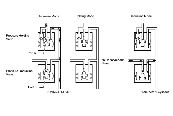
Not Activated Normal Braking - - Activated Increase Mode Holding Mode Reduction Mode Pressure Holding Solenoid Valve Off (Open) On (Closed) ← Pressure Reduction Solenoid Valve Off (Closed) ← On (Open) Wheel Cylinder Pressure Increased Held Reduced
-
-
Brake Assist Operation
-
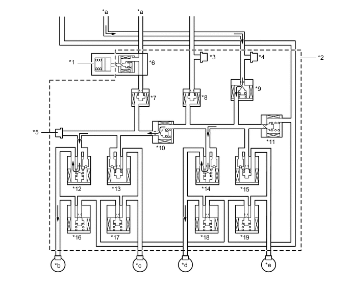
In the event of emergency braking, the skid control ECU detects the driver's intention based on the speed of the pressure increase in the brake master cylinder determined by the regulator pressure sensor signal. If the skid control ECU judges the need for additional brake assist, the fluid pressure from the accumulator is directed to the wheel cylinder to apply a greater fluid pressure than the regulator chamber.

*1 Brake Master Stroke Simulator Cylinder Assembly *2 Brake Actuator *3 Regulator Pressure Sensor *4 Accumulator Pressure Sensor *5 Wheel Cylinder Pressure Sensor *6 Switching Solenoid Valve SSC *7 Switching Solenoid Valve SMC *8 Switching Solenoid Valve SRC *9 Linear Solenoid Valve SLA *10 Switching Solenoid Valve SCC *11 Linear Solenoid Valve SLR *12 Pressure Holding Solenoid Valve FLH *13 Pressure Holding Solenoid Valve FRH *14 Pressure Holding Solenoid Valve RLH *15 Pressure Holding Solenoid Valve RRH *16 Pressure Reduction Solenoid Valve FLR *17 Pressure Reduction Solenoid Valve FRR *18 Pressure Reduction Solenoid Valve RLR *19 Pressure Reduction Solenoid Valve RRR - - *a From Brake Master Cylinder *b Front Brake LH *c Front Brake RH *d Rear Brake LH *e Rear Brake RH - - Item Normal Braking Increase Mode Brake Assist Activated Linear Solenoid Valve SLA On (Half-open*) ← SLR Off (Closed) ← Switching Solenoid Valve SSC On (Open) ← SCC On (Open) ← SMC On (Closed) ← SRC On (Closed) ← Pressure Holding Solenoid Valve FLH Off (Open) ← FRH Off (Open) ← RLH Off (Open) ← RRH Off (Open) ← Pressure Reduction Solenoid Valve FLR Off (Closed) ← FRR Off (Closed) ← RLR Off (Closed) ← RRR Off (Closed) ← Tech Tips
*: The solenoid valve constantly regulates the amount of opening of the valve in accordance with the use conditions in order to control the fluid pressure.
-
-
TRC Operation
-
The fluid pressure stored in the accumulator is regulated by the switching solenoid valves and control solenoid valves to the required pressure. Thus, the wheel cylinders of the drive wheels are controlled in the following 3 modes: pressure reduction, pressure holding and pressure increase modes to control the slippage of the drive wheels. The diagram below shows the hydraulic circuit in pressure increase mode when the TRC is activated. Each pressure holding solenoid valve and pressure reduction solenoid valve is turned on or off according to the ABS operation pattern.
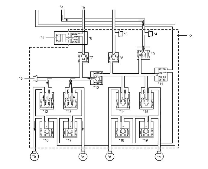
*1 Brake Master Stroke Simulator Cylinder Assembly *2 Brake Actuator *3 Regulator Pressure Sensor *4 Accumulator Pressure Sensor *5 Wheel Cylinder Pressure Sensor *6 Switching Solenoid Valve SSC *7 Switching Solenoid Valve SMC *8 Switching Solenoid Valve SRC *9 Linear Solenoid Valve SLA *10 Switching Solenoid Valve SCC *11 Linear Solenoid Valve SLR *12 Pressure Holding Solenoid Valve FLH *13 Pressure Holding Solenoid Valve FRH *14 Pressure Holding Solenoid Valve RLH *15 Pressure Holding Solenoid Valve RRH *16 Pressure Reduction Solenoid Valve FLR *17 Pressure Reduction Solenoid Valve FRR *18 Pressure Reduction Solenoid Valve RLR *19 Pressure Reduction Solenoid Valve RRR - - *a From Brake Master Cylinder *b Front Brake LH *c Front Brake RH *d Rear Brake LH *e Rear Brake RH - - Item TRC not Activated TRC Activated Increase Mode Holding Mode Reduction Mode Linear Solenoid Valve SLA Off (Closed) On (Open) ← ← SLR Off (Closed) ← ← ← Switching Solenoid Valve SSC On (Open) ← ← ← SCC On (Open) ← ← ← SMC Off (Open) On (Closed) ← ← SRC Off (Open) On (Closed) ← ← Pressure Holding Solenoid Valve FLH Off (Open) ← On (Closed) ← FRH Off (Open) ← On (Closed) ← RLH Off (Open) On (Closed) ← ← RRH Off (Open) On (Closed) ← ← Pressure Reduction Solenoid Valve FLR Off (Closed) ← ← On (Open) FRR Off (Closed) ← ← On (Open) RLR Off (Closed) ← ← ← RRR Off (Closed) ← ← ←
-
-
VSC Operation
-
The VSC uses solenoid valves to control the fluid pressure that is stored in the accumulator and apply it to the brake wheel cylinder of each wheel in the following 3 modes: pressure reduction, pressure holding and pressure increase modes. As a result, the tendency of front wheel skid or rear wheel skid is controlled.
-
In front wheel skid restraining control, the brakes of the front wheels and rear wheel of the inner circle of the turn are applied. Also, depending on whether the brake is on or off and the operating conditions of the vehicle, there are circumstances in which the brake might not be applied to the wheels even if the wheel is targeted for braking. The diagram below shows the hydraulic circuit in pressure increase mode, as it controls a front wheel skid condition while the vehicle is making a right turn. In other operating modes, each pressure holding valve and pressure reduction valve is turned on or off according to the ABS operation pattern.
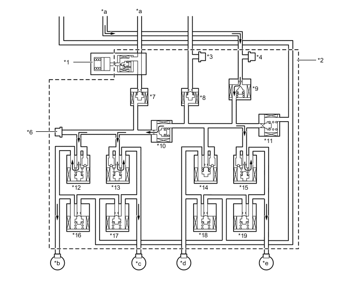
*1 Brake Master Stroke Simulator Cylinder Assembly *2 Brake Actuator *3 Regulator Pressure Sensor *4 Accumulator Pressure Sensor *5 Wheel Cylinder Pressure Sensor *6 Switching Solenoid Valve SSC *7 Switching Solenoid Valve SMC *8 Switching Solenoid Valve SRC *9 Linear Solenoid Valve SLA *10 Switching Solenoid Valve SCC *11 Linear Solenoid Valve SLR *12 Pressure Holding Solenoid Valve FLH *13 Pressure Holding Solenoid Valve FRH *14 Pressure Holding Solenoid Valve RLH *15 Pressure Holding Solenoid Valve RRH *16 Pressure Reduction Solenoid Valve FLR *17 Pressure Reduction Solenoid Valve FRR *18 Pressure Reduction Solenoid Valve RLR *19 Pressure Reduction Solenoid Valve RRR - - *a From Brake Master Cylinder *b Front Brake LH *c Front Brake RH *d Rear Brake LH *e Rear Brake RH - - Item VSC not Activated VSC Activated Increase Mode Holding Mode Reduction Mode Linear Solenoid Valve SLA Off (Closed) On (Open) ← ← SLR Off (Closed) ← ← ← Switching Solenoid Valve SSC On (Open) ← ← ← SCC On (Open) ← ← ← SMC Off (Open) On (Closed) ← ← SRC Off (Open) On (Closed) ← ← Pressure Holding Solenoid Valve FLH Off (Open) ← On (Closed) ← FRH Off (Open) ← On (Closed) ← RLH Off (Open) On (Closed) ← ← RRH Off (Open) ← On (Closed) ← Pressure Reduction Solenoid Valve FLR Off (Closed) ← ← On (Open) FRR Off (Closed) ← ← On (Open) RLR Off (Closed) ← ← ← RRR Off (Closed) ← ← On (Open) -
In rear wheel skid restraining control, the brakes of the front and rear wheels on the outer circle of the turn are applied. Also, depending on whether the brake is on or off and the operating conditions of the vehicle, there are circumstances in which the brake might not be applied to the wheels even if the wheel is targeted for braking. The diagram below shows the hydraulic circuit in the pressure increase mode, as it controls a rear wheel skid condition while the vehicle is making a right turn. In other operating modes, each pressure holding valve and pressure reduction valve is turned on or off according to the ABS operation patterns.
*1 Brake Master Stroke Simulator Cylinder Assembly *2 Brake Actuator *3 Regulator Pressure Sensor *4 Accumulator Pressure Sensor *5 Wheel Cylinder Pressure Sensor *6 Switching Solenoid Valve SSC *7 Switching Solenoid Valve SMC *8 Switching Solenoid Valve SRC *9 Linear Solenoid Valve SLA *10 Switching Solenoid Valve SCC *11 Linear Solenoid Valve SLR *12 Pressure Holding Solenoid Valve FLH *13 Pressure Holding Solenoid Valve FRH *14 Pressure Holding Solenoid Valve RLH *15 Pressure Holding Solenoid Valve RRH *16 Pressure Reduction Solenoid Valve FLR *17 Pressure Reduction Solenoid Valve FRR *18 Pressure Reduction Solenoid Valve RLR *19 Pressure Reduction Solenoid Valve RRR - - *a From Brake Master Cylinder *b Front Brake LH *c Front Brake RH *d Rear Brake LH *e Rear Brake RH - - Item VSC not Activated VSC Activated Increase Mode Holding Mode Reduction Mode Linear Solenoid Valve SLA Off (Closed) On (Open) ← ← SLR Off (Closed) ← ← ← Switching Solenoid Valve SSC On (Open) ← ← ← SCC On (Open) ← ← ← SMC Off (Open) On (Closed) ← ← SRC Off (Open) On (Closed) ← ← Pressure Holding Solenoid Valve FLH Off (Open) ← On (Closed) ← FRH Off (Open) On (Closed) ← ← RLH Off (Open) ← On (Closed) ← RRH Off (Open) On (Closed) ← ← Pressure Reduction Solenoid Valve FLR Off (Closed) ← ← On (Open) FRR Off (Closed) ← ← ← RLR Off (Closed) ← ← On (Open) RRR Off (Closed) ← ← ←
-
-
VSC+ Operation
-
The operation of the solenoid valves under the cooperative control is the same as the TRC or VSC operation.
-
-
Hill-start Assist Control Operation
-
Hill-start assist control operation is performed by closing the pressure holding solenoid valve after the driver operates the brake pedal and leaving a certain amount of hydraulic pressure created by the brake booster pump assembly in the wheel cylinder. The diagram below shows the hydraulic circuit in the pressure holding mode.
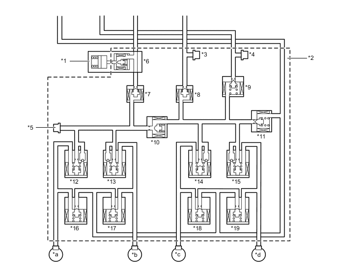
*1 Brake Master Stroke Simulator Cylinder Assembly *2 Brake Actuator *3 Regulator Pressure Sensor *4 Accumulator Pressure Sensor *5 Wheel Cylinder Pressure Sensor *6 Switching Solenoid Valve SSC *7 Switching Solenoid Valve SMC *8 Switching Solenoid Valve SRC *9 Linear Solenoid Valve SLA *10 Switching Solenoid Valve SCC *11 Linear Solenoid Valve SLR *12 Pressure Holding Solenoid Valve FLH *13 Pressure Holding Solenoid Valve FRH *14 Pressure Holding Solenoid Valve RLH *15 Pressure Holding Solenoid Valve RRH *16 Pressure Reduction Solenoid Valve FLR *17 Pressure Reduction Solenoid Valve FRR *18 Pressure Reduction Solenoid Valve RLR *19 Pressure Reduction Solenoid Valve RRR - - *a Front Brake LH *b Front Brake RH *c Rear Brake LH *d Rear Brake RH Item Hill-start Assist not Activated Hill-start Assist Activated Holding Mode Reduction Mode Linear Solenoid Valve SLA Off (Closed) ← ← SLR Off (Closed) ← On (Open) Switching Solenoid Valve SSC On (Open) ← ← SCC On (Open) ← ← SMC Off (Open) On (Closed) ← SRC Off (Open) On (Closed) ← Pressure Holding Solenoid Valve FLH Off (Open) ← ← FRH Off (Open) ← ← RLH Off (Open) ← ← RRH Off (Open) ← ← Pressure Reduction Solenoid Valve FLR Off (Closed) ← ← FRR Off (Closed) ← ← RLR Off (Closed) ← ← RRR Off (Closed) ← ←
-
-