HYBRID TRANSAXLE SYSTEM
-
CONSTRUCTION
-
The parking lock actuator (shift control actuator assembly) consists of a switched reluctance motor and a cycloid reduction mechanism.
-
The parking lock actuator (shift control actuator assembly) is mounted on the side of the FCV transaxle assembly. Upon receiving an actuation signal from the transmission control ECU assembly, the motor rotates to engage or disengage the parking lock mechanism. As a result, the transaxle is locked or unlocked mechanically.
-
The switched reluctance motor is mainly composed of a coil, a stator, rotor and rotation angle sensor. Brushes and permanent magnets are not used.
-
The rotation angle sensor consists of 2 Hall ICs. The 2 of them, one for phase A, and one for phase B, are used to detect the rotation angle of the motor.
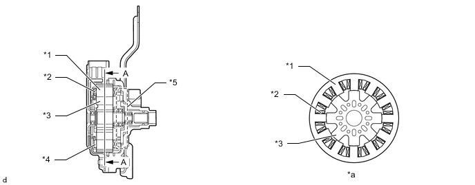
*1 Stator *2 Coil *3 Rotor *4 Rotation Angle Sensor *5 Cycloid Reduction Mechanism - - *a A-A Cross Section - -
-
Cycloid Reduction Mechanism
-
The cycloid reduction mechanism ensures the complete releasing operation of the parking lock when the vehicle is parked on a sloping road that requires a high amount of torque to release the parking lock, since it amplifies the torque of the motor output shaft.
-
This mechanism consists of an eccentric plate that is mounted on the motor output shaft, an inside gear (61 teeth) that is secured to the housing, an outside gear (60 teeth), and an output shaft that rotates in unison with the outside gear.
-
Along with the rotational movement of the eccentric plate, which rotates in unison with the motor output shaft, the inside gear pushes against the outside gear while meshing. The outside gear, which has 1 tooth less than the inside gear, rotates 1 tooth less per rotation of the eccentric plate. As a result, the output shaft, which rotates in unison with the outside gear, outputs the rotational movement of the motor at a reduction ratio of 61:1.
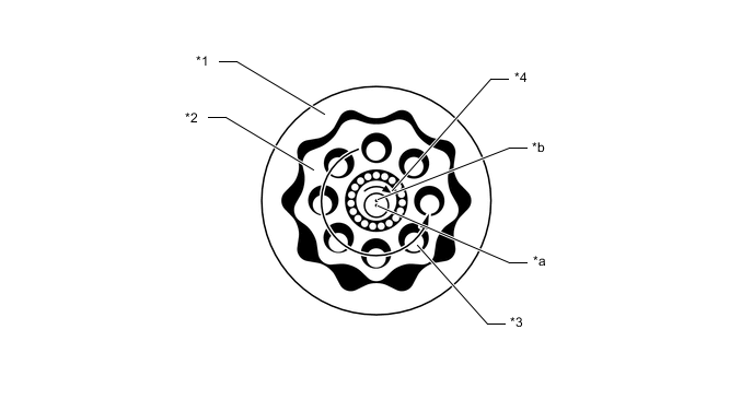
*1 Inside Gear *2 Outside Gear *3 Output Shaft *4 Eccentric Plate *a Motor Input Shaft Center *b Eccentric Plate Center
-
-