HYDROGEN CONTROL SYSTEM
-
CONSTRUCTION
-
Hydrogen Tank Assembly
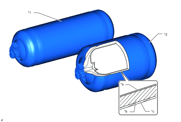
*1 No. 1 Hydrogen Tank Assembly *2 No. 2 Hydrogen Tank Assembly *a Plastic Liner *b Carbon Fiber Reinforced Plastic (CFRP) Layer *c Glass Fiber Reinforced Plastic (GFRP) Layer - - Parts Function Plastic Liner Suppresses hydrogen gas permeation Carbon Fiber Reinforced Plastic (CFRP) Layer Reinforces the plastic liner Glass Fiber Reinforced Plastic (GFRP) Layer Protects the surface layer
-
The hydrogen tank is designed to handle a high filling pressure (87.5 MPa (892.3 kgf/cm2, 12688 psi)). There are 2 hydrogen tanks placed under the floor in the rear of the vehicle, providing substantial cruising distance.
-
A hydrogen tank optimized for fuel cell vehicle use and composed primarily of carbon fiber reinforced plastic has been adopted.
Note
-
The hydrogen related components (such as the tanks, pipelines, etc.) have expiration dates established by law. Vehicle with expired hydrogen related components must not be used. The hydrogen related components must be replaced with new ones if their expiration dates have passed. The expiration date is written on the inside of the fuel door as the limit date of filling. Consult any authorized Toyota dealer or repairer, or another duly qualified and equipped professional.
-
When disposing of the hydrogen tanks or the hydrogen tank valves, consult any authorized Toyota dealer or repairer, or another duly qualified and equipped professional for details.
-
-
Each hydrogen tank is installed to the vehicle body with 2 tank bands. Each tank band is equipped with springs to absorb the expansion that occurs when the tanks are filled.
-
-
Hydrogen tank valve
-
Hydrogen tank valves are installed to each hydrogen tank, and perform fuel supply and shutoff.
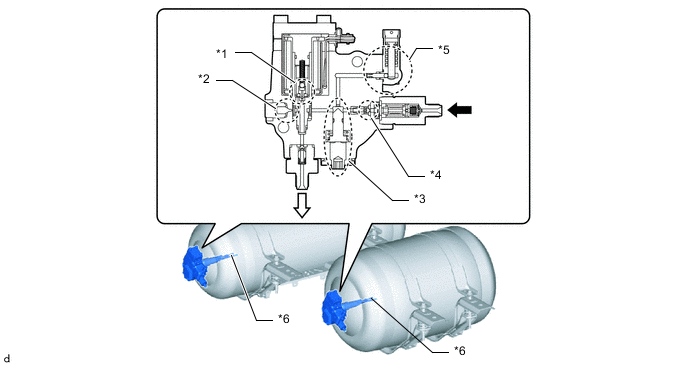
*1 Tank Shut Valve *2 Defueling Valve *3 Manual Valve *4 Check Valve *5 Pressure Relief Device *6 Hydrogen Tank Temperature Sensor 
from Receptacle 
to Regulator Tank Shut Valve
-
In the event of a hydrogen gas leak, the hydrogen gas is detected and the electromagnetic valve closes, stopping the leakage of hydrogen gas.
-
If a collision is detected, the electromagnetic valve closes, preventing the leakage of large amounts of hydrogen gas.
Defueling Valve Manually operated to release the gas in the hydrogen tank into the atmosphere. Under normal circumstances this valve is not used and remains closed. If the electromagnetic valve has malfunctioned in the closed position and the gas in the hydrogen tank cannot be removed, this valve can be opened to release the gas from the hydrogen tank. Manual Valve Manually operated to stop the flow of hydrogen gas. This valve remains open in normal use. When storing a tank by itself, or when performing a leak check of the high pressure joints, this valve is operated to shut off the connection between the fuel lines and the hydrogen tank. Check Valve Pushed open by gas pressure during refueling. Hydrogen fuel that has been filled into the hydrogen tank is prevented from flowing in the reverse direction. Pressure Relief Device When a vehicle fire has occurred, in order to reduce the occurrence of hydrogen tank rupture, the hydrogen gas inside the hydrogen tank is vented from the pressure relief device to the rear of the vehicle in a downwards diagonal direction. Move away from the vehicle in the event of a fire. Hydrogen Tank Temperature Sensor Detects the hydrogen temperature inside the hydrogen tank. -
-
-