FC CONTROL SYSTEM
-
CONSTRUCTION
-
The FC stack assembly is a device that uses a chemical reaction between hydrogen and oxygen to generate electrical energy.
-
The FC stack assembly is composed of the 370 layers of fuel cells, FC stack monitor, hydrogen system components (hydrogen pump, injector, etc.), air system components (air diverter valve, air pressure regulator valve, etc.), cooling system components, high voltage components, etc.
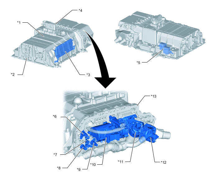
*1 FC Stack Assembly *2 FC Stack Ventilation Cover *3 FC Stack Monitor *4 FC Service Plug Grip *5 FC Main Relay *6 Low-range Hydrogen Pressure Sensor *7 Hydrogen Injector *8 Pressure Relief Valve *9 Medium-range Hydrogen Pressure Sensor *10 Hydrogen Pump *11 Air Pressure Regulating Valve *12 Air Shunt Valve *13 Stack manifold - - -
The FC service plug grip has been provided to shut off the high voltage circuits, ensuring technician safety during service operations.
-
Hydrogen system components and air system components have been grouped in the area around the FC stack assembly and given improved controllability, enabling reductions in mass and bulk.
-
FC stack
-
The FC stack is composed of 370 fuel cells connected in series.
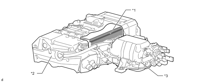
*1 FC Stack *2 FC Stack Assembly *3 FC Converter Assembly - -
-
-
FC stack monitor
-
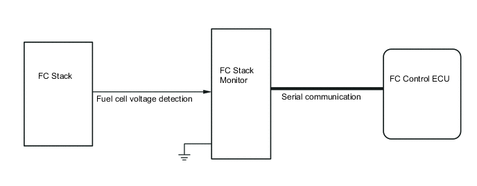
The FC stack monitor detects the FC stack condition (voltage) and sends it to the FC control ECU.
-
-
FC main relay
-
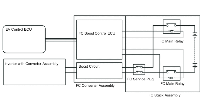
The FC main relay is controlled by the FC boost control ECU (built into FC converter assembly), and is the relay that connects and disconnects the high voltage circuits coming out of the FC stack. Relays are installed on both the positive and negative lines of the FC stack output.
-
When a relay actuation command is received from the EV control ECU, the FC boost control ECU (built into FC converter assembly) operates the actuation circuit to drive the FC main relay and connect or disconnect the high voltage circuits.
-
-
Stack case
-
The stack case contains many high voltage components, and for these components the case performs the functions of containing, waterproofing, dustproofing, and providing protection against contact with high voltage.
-
Because the stack case is located in the vehicle underfloor environment, it has been anodized for superior corrosion resistance.
-
-
Lower cover
-
The lower cover installed to the underside of the FC stack assembly provides the internal high voltage components with waterproofing, dustproofing and protection against contact, as well as electromagnetic shielding and protection against flying stones.
-
The strength of the cover is the same as a normal oil pan, and it is resistant to rust.
-
-
FC stack ventilation cover
-
The FC stack ventilation cover protects the system by preventing muddy water, dust, etc. from entering the case, and is also ventilated to so that the average hydrogen concentration inside the stack case is less than 4%. Also, there are 3 covers on the left side, where the hydrogen permeation amount is higher, and 1 on the right side where it is lower.
-
The FC stack ventilation cover is composed of a housing made of plastic resin and a ventilation membrane.
-
An extremely fine porous membrane made of fluorocarbon polymer is used for efficient hydrogen permeation.
-
To prevent blockage of the pores of the membrane, it is treated to repel both water and oil.
-
-
-
Stack manifold
-
The stack manifold is composed of the passages for hydrogen, air, and coolant, has the functions of insulating the high voltage areas (electrical generating areas) inside the stack and load holding to keep the FC stack under compression, and is made of one-piece molded resin and aluminum to realize compactness and improved dimensional precision.
-
-
Gas-liquid separator
-
The gas-liquid separator is located in the hydrogen circulation system of the FC stack assembly, and from the hydrogen circulation system it separates the water produced during electrical generation, as well as the nitrogen permeating from the air side.
-
-
Exhaust drain valve
-
The generated water and the nitrogen gas separated out by the gas-liquid separator are exhausted and drained to the exhaust pipe.
-
-