HYBRID TRANSAXLE SYSTEM
-
CONSTRUCTION
-
Traction Motor
-
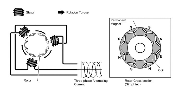
Compact, lightweight and high efficiency permanent magnet synchronous motors are used for the traction motor.
-
The traction motor, to provide excellent power performance as a power source. In addition, at the time of the regenerative braking it will convert the kinetic energy of the vehicle into electric energy.
-
When three-phase alternating current is applied to the three-phase winding of the stator coil, rotation of the magnetic field is created in the motor. This rotation of the magnetic field is controlled based on the rotation position and speed of the rotor to pull the permanent magnet located in the rotor towards the magnetic field, thereby producing torque. This torque, for all practical purposes, is proportional to the current, and the speed is controlled based on the frequency of the alternating current. Additionally, the rotation of the magnetic field and the angle of the rotor magnet are accurately controlled to efficiently generate high torque even at high speeds.
-
When generating power, rotation of the rotor creates a magnetic field, inducing current flow in the stator coil.
-
For the traction motor, the permanent magnets in the rotors are optimally located to efficiently use reluctance torque*. This amplifies the rotational force of the rotor, helping to enhance driving force.
Tech Tips
*: Torque generated due to the changes in magnetic reluctance in the gap between the stator and rotor.
Figure 1. Power Generation
-
-
-
Rotation Sensor (Resolver Type)
-
The resolver type rotation sensors are compact, reliable sensors, which accurately detect the location of the magnets, which is necessary to efficiently control the traction motor.
-
The stator of a rotation sensor employs 3 coils as shown in the illustration. Output coil S and output coil C are arranged at a 90° angle to each other.
-
Because the excitation coil of the resolver is provided with alternating current at a constant frequency, a constant frequency magnetic field is output to coils S and C, regardless of rotor speed. The magnetic field of the excitation coil is carried to coils S and C by the rotor. The rotor is oval, and the gap between the stator of the resolver and the its rotor varies with the rotation of the rotor. Due to the variation of the gap, the peak values of the waveforms output by coils S and C vary in accordance with the position of the rotor.
-
The Motor Generator ECU (MG ECU) constantly monitors these peak values, and connects them to form a virtual waveform. The Motor Generator ECU (MG ECU) calculates the absolute position of the rotor from the difference between the values of the coils S and C. It determines the rotor direction based on the difference between the phases of the virtual waveform of the coil S and the virtual waveform of the coil C. Furthermore, the Motor Generator ECU (MG ECU) calculates the rotational speed based on the amount of change in the rotor position within a given length of time.
-
The following illustration shows waveforms of excitation coil A, output coil S and output coil C when the rotor rotates 180° in the positive (+) direction.
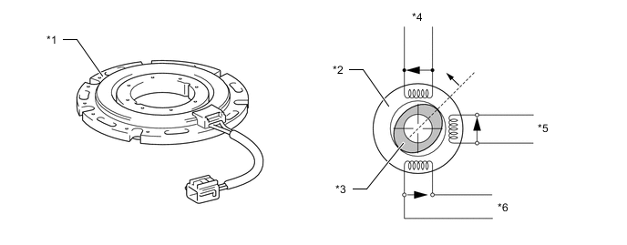
*1 Rotation Sensor (Resolver) *2 Stator *3 Rotor *4 Excitation Coil A *5 Output Coil S *6 Output Coil C Figure 2. Rotation Sensor Output Waveform (Conceptual Image Shown)
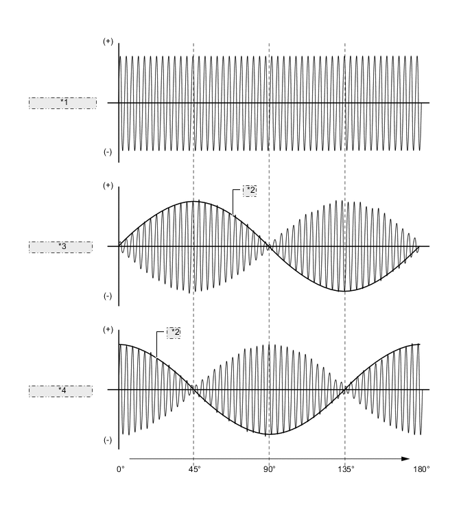
*1 Excitation Coil A *2 Virtual Waveform *3 Detection Coil S *4 Detection Coil C
-
-
Temperature Sensor
-
A temperature sensor is provided for the traction motor to detect the stator temperature.
-
EV control ECU, based on the signal from the temperature sensor, and optimally controlling the traction motor.
-
-