HYBRID CONTROL SYSTEM
-
CONSTRUCTION
-
The MG ECU, inverter, boost converter, and DC-DC converter are combined into a single body, the compact and lightweight inverter with converter assembly. The inverter and boost converter are mainly composed of the IPMs (Intelligent Power Module) that handle vehicle driving, FC air compressor driving, electrical generation and voltage boosting, and also the reactor and capacitor.
-
The MG ECU controls the inverter and boost converter according to output request values from the EV control ECU.
-
The boost converter boosts the EV battery voltage from DC 244.8 V to a maximum of DC 650 V. In this way, the FC air compressor motor and the traction motor are driven at high voltage, providing higher output power and reducing electrical losses.
-
The inverter takes the high voltage DC current boosted by the boost converter and the high voltage DC current from the FC stack and changes it to AC current to supply the FC air compressor motor and the traction motor. Also, when the traction motor is used as a generator, it changes the generated AC current to DC current.
-
To optimally control the inverter and boost converter, the inverter with converter assembly contains a number of sensors such as the inverter current sensor, inverter temperature sensor and atmospheric pressure sensor.
-
The DC-DC converter steps down the EV battery voltage from DC 244.8 V to approximately DC 14 V to supply to the auxiliary battery and auxiliary components.
-
The inverter terminal cover and power supply branching box connecting portion have an interlock switch to detect the installation condition. If the inverter terminal cover is removed or the power supply branching box is disconnected, the interlock switch turns off and the SMR (System Main Relay) will be shut off.
-
The inverter with converter assembly has the EV cooling system, which is independent from the FC cooling system. The coolant directly cools the IPMs that handle vehicle driving, FC air compressor driving, electrical generation and voltage boosting, providing a high level of heat dissipation when the system is in operation, contributing to the compactness of the inverter with converter assembly.
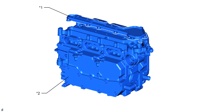
*1 Inverter Terminal Cover *2 Inverter with Converter Assembly 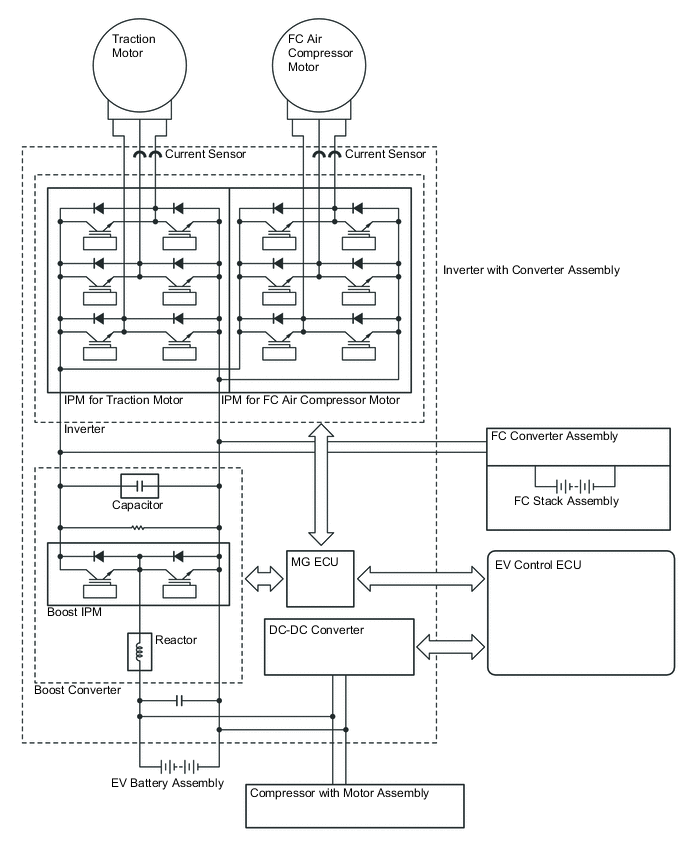
-
Inverter
-
The inverter converts the boosted high-voltage direct current of the HV battery into 3 phase alternating current to drive the FC air compressor motor and the traction motor.
-
The activation of the power transistors is controlled by the MG ECU. Additionally, the inverter sends information that is necessary for current control, such as the output amperage and voltage, to the EV control ECU via the MG ECU.
-
The power transistors used in the inverter are Insulated Gate Bipolar Transistors (IGBTs).
-
-
Boost Converter
-
The boost converter uses a boost IPM to perform switching control, a reactor to act as an inductor, and a capacitor to accumulate and store electricity. The boost IPM uses IGBT2 for boosting voltage, and IGBT1 for reducing voltage.
-
-
DC-DC converter
-
The DC-DC converter steps down the EV battery voltage from DC 244.8 V to approximately DC 14 V to supply to the auxiliary battery and auxiliary components.
-
-
MG ECU
-
The MG ECU is built into the inverter with converter assembly, and following the output request values from the EV control ECU, operates the IPMs that handle vehicle driving, FC air compressor driving, electrical generation and voltage boosting, and controls the inverter and boost converter. Also, the MG ECU sends the information necessary for vehicle control, such as the inverter output current value, voltage, inverter with converter assembly internal temperature sensors and atmospheric pressure sensor, to the EV control ECU.
-
When the MG ECU drives the FC air compressor and the traction motor, it uses the boost converter to boost the voltage of the DC current from the EV battery.
-
The MG ECU uses the inverter to change DC current into 3 phase AC current, and performs current control. Also, when the traction motor operates as a generator, the AC current generated by the traction motor through regenerative braking is changed to DC current and stepped down to a lower voltage to charge the EV battery.
Main Functions of MG ECU Control Function Inverter Control FC Air Compressor Control Drives the FC air compressor according to FC air request values from the FC control ECU. Traction Motor Control
-
Drives the traction motor following output request values from the EV control ECU, which are made according to the torque requested by the driver.
-
Controls the traction motor to function as a generator when there is a regenerative braking request from the skid control ECU (brake booster with master cylinder assembly).
Boost Converter Control Boosts the voltage from the EV battery from DC 244.8 V to a maximum of DC 650 V and outputs it to the inverter. Also, when the traction motor has generated electricity that has been changed to DC at a maximum of 650V by the inverter, it is stepped down to DV 244.8 V in order to charge the EV battery. -
-
-
Current Sensor (for Inverter with Converter Assembly)
-
For the 3-phase AC used to drive the FC air compressor motor and traction motor, there are current sensors for the V and W phases. The actual current value is measured and used as feedback by the MG ECU.
Figure 1. Characteristics of Inverter Current Sensor:
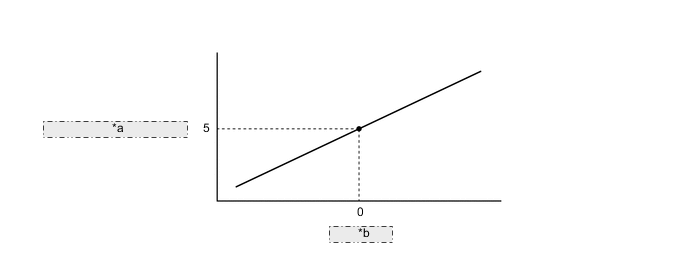
*a Sensor Output Voltage (V) *b Current (A) -
-
Temperature Sensor (for Inverter with Converter Assembly)
-
For the inverter with converter assembly, there are 5 different temperature sensors; 2 of them are located at the IPMs for FC air compressor motor and the traction motor, 2 of them are located at the boost converter, and the remaining sensor is located at the EV coolant passage.
-
These sensors detect the temperatures at areas inside the inverter with converter assembly, and transmit that temperature information to the EV control ECU via the MG ECU. The EV control ECU optimizes the cooling system according to the temperature information, maintaining the output performance of the inverter with converter assembly.
-
-
Atmospheric Pressure Sensor
-
The atmospheric pressure sensor is provided on the MG ECU board.
-
This sensor detects the atmospheric pressure and transmits a signal to the MG ECU to allow corrections that correspond to the usage environment.
-
-
-