HYBRID CONTROL SYSTEM
-
FUNCTION OF MAIN COMPONENTS
Component Function EV Control ECU
-
Performs driving and electrical distribution based on the signals from each sensor and ECU.
-
Monitors the EV battery condition (battery voltage / current / temperature)
-
Controls the EV water pump with motor assembly to adjust the output quantity.
-
Sends radiator cooling fan operation request signals to the FC control ECU.
-
Controls the battery cooling blower assembly to adjust the blower output.
-
Performs cooperative control with the skid control ECU and regenerative breaking system.
-
Actuates the SMR to connect and disconnect the high voltage circuits from the EV battery.
-
Controls the DC-DC converter to step down the DC 244.8 V of the EV battery to DC 14 V.
FC Control ECU Based on FC output request from the EV control ECU, the hydrogen supply amount, oxygen supply amount and FC stack coolant temperature are controlled to optimal levels. Accelerator Pedal Sensor Assembly Detects the accelerator opening angle and sends it to the EV control ECU. Transmission Instrument Panel Shift Assembly Shift Sensor Detects the vertical motion of the shift lever and sends it to the EV control ECU. Select Sensor Detects the horizontal motion of the shift lever and sends it to the EV control ECU. Inverter with Converter Assembly MG ECU According to the output value requested from the EV control ECU, operates the inverter and boost converter, and controls the traction motor and FC air compressor. Inverter Converts between high voltage DC and three phase AC. Converter
-
Boosts the EV battery assembly voltage to a maximum of DC 650 V.
-
Steps down the FC stack assembly voltage and the high voltage (max. 650 V) from the inverter.
DC-DC Converter Steps down the voltage of the high voltage system to approximately DV 14 V and provides it to accessory components and the auxiliary battery. FCV Transaxle with Motor Assembly Traction Motor Based on driving conditions, uses the electrical energy from the FC stack assembly and the electrical energy from the EV battery assembly to generate driving force. Also, uses regenerative braking to generate electricity when decelerating. FC Air Compressor with Motor Assembly
-
Supercharges the air that has passed the air cleaner and provides it to the FC stack assembly.
-
Driven by the inverter of the inverter with converter assembly.
FC Stack Assembly FC Stack Generates electrical energy by causing a chemical reaction between hydrogen fuel from the hydrogen tank and oxygen from the FC air compressor with motor assembly. FC Stack Monitor Detects the output voltage of the FC and sends it to the FC control ECU. FC Main Relay Based on the signal from the FC boost control ECU, connects and disconnects the high voltage circuits of the FC stack assembly. FC Service Plug Grip Removed during inspection or service to disconnect the high voltage circuits of the FC stack assembly. FC Converter Assembly FC Boost Converter Boosts the voltage of the electrical energy generated in the FC stack assembly to a maximum of DC 650 V. FC Boost Control ECU According to requests from the EV control ECU, connects and disconnects the FC main relay and controls the electric power to match the value specified by the electric power request. EV Battery Assembly Battery Modules
-
Stores the electrical power generated by the FC stack as well as the electrical power regenerated through regenerative braking of the traction motor.
-
Supplies electrical power to the traction motor when starting out, accelerating, etc.
Battery Voltage Sensor Sends EV battery status signals (battery temperature, voltage, current value) to the EV control ECU. SMR (System Main Relay) Connects and disconnects the high voltage circuits of the EV battery based on the signals from the EV control ECU. Service Plug Grip Removed during inspection or service to disconnect the high voltage circuits of the EV battery. Integration Control and Panel Assembly P Position Switch Sends the P position switch operation signal to the EV control ECU. ECO Mode Switch Changes the driving mode to Eco mode. POWER Mode Switch Changes the driving mode to Power mode. Stop Light Switch Assembly Detects the brake pedal on/off condition. Auxiliary Battery Temperature Sensor (Thermistor Assembly) Detects the temperature of the auxiliary battery in order to control the output voltage of the DC-DC converter. EV Water Pump with Motor Assembly Circulates coolant in order to cool the inverter with converter assembly and FC air compressor motor. Skid Control ECU (Brake Booster with Master Cylinder Assembly)
-
When braking, calculates the necessary regenerative braking force and sends it to the EV control ECU, and at the same time controls the hydraulic brakes.
-
When TRC or VSC operating, sends requested torque to the EV control ECU, and controls driving force.
-
Sends the motor traction control requested torque to the EV control ECU, and controls braking force of the brakes.
Airbag ECU Assembly In a collision, sends the collision detection signal to the EV control ECU. Air Conditioning Amplifier Assembly Sends the motor compressor assembly speed control instruction signal and heater water pump assembly drive request signal to the EV control ECU, and controls the air conditioner system. Combination Meter Assembly Energy Monitor Displays the FC system output status via the energy monitor. READY Indicator Light Indicates a status in which driving is possible. Master Warning Light When there is a system malfunction, the light illuminates depending on the malfunction. ECO Mode Indicator Light Indicates that ECO mode is selected. POWER Mode Indicator Light Indicates that POWER mode is selected. Auxiliary Battery Warning Light When there is a DC-DC converter malfunction, the light illuminates depending on the malfunction. Hydrogen Leak Warning Light Illuminates when a hydrogen leak has been detected. Shift Position Indicator Light Displays the selected shift position. Multi-Buzzer When there is a system malfunction, the buzzer sounds depending on the contents of the malfunction. -
-
SYSTEM CONTROL
-
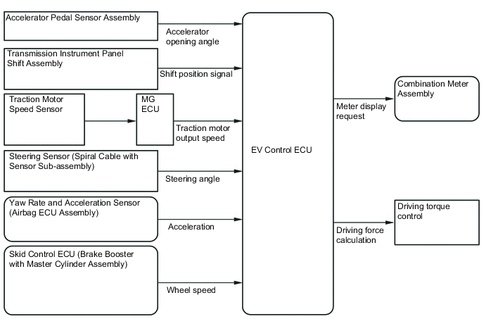
Based on a number of driving conditions, the EV control ECU provides an optimum amount of electrical energy to the traction motor to realize smooth and powerful driving in response to driver demands. Also, it monitors and controls EV battery conditions and high voltage circuits, uses cooperative control with the skid control ECU for regenerative braking, etc., and comprehensively performs various controls relating to the FC system.
System Control List Item Function FC System Output Control
-
Based on the accelerator opening angle signal, shift position signal and vehicle speed signal, the EV control ECU performs control of FC system output by calculating the FC stack electrical output power, FC air compressor motor torque and the traction motor torque according to the driver request, and sending requested values to the FC control ECU and MG ECU.
FC Stack Electrical Power and Boost Control
-
The FC boost ECU controls the electrical output power from the FC stack so that it becomes a power value matching the command request from the EV control ECU, while at the same time boosting the voltage to 650 V.
Brake Cooperative Control and Regenerative Brake Control
-
When decelerating, the skid control ECU calculates the necessary regenerative braking force and sends the value to the EV control ECU. When this happens, the EV control ECU sends the actual regenerative braking value to the skid control ECU, and based on this, the skid control ECU controls the hydraulic braking force.
Collision Control
-
When an airbag deployment signal from the airbag ECU assembly is detected, the high voltage circuits and hydrogen fuel supply lines are shut off.
Brake Override Control
-
The driving torque is restricted when both the accelerator and brake pedals are depressed. (For the Activation Conditions and Inspection Method, refer to the Repair Manual)
Drive Start Control System
-
Even if the driver is in a hurry and abnormal accelerator pedal and shift operations are performed, vehicle speed and acceleration are restricted to improve the sense of security felt by the driver.
-
-
FC System Activation
-
The FC system can be activated by pressing the power switch while the brake pedal is being depressed.
Tech Tips
When starting and stopping, the FC main relay built into the FC stack and the hydrogen tank valve installed to the hydrogen tank are actuated, which causes an operating sound to be heard.
-
If the FC stack coolant temperature is low (approximately -10°C (14°F) or lower) at the time the FC system is started, startup time will become longer and so the following screen will be displayed on the multi-information display in the combination meter assembly.
Figure 1. Multi-information Display Screen

-
When the vehicle is driven in cold ambient temperatures (approximately -10°C (14°F) or lower), in addition to the normal start/stop sequence, rapid warmup will be performed when the vehicle starts, and freezing prevention processing will be performed when stopping. This ensures startability when in low temperature areas.
-
-
While the FC system is starting up, pressing the power switch again will stop the system.
-
While the vehicle is being driven, power switch operation is cancelled.*
Tech Tips
*: If a situation arises in which it is absolutely necessary to stop the FC system while the vehicle is being driven, rapidly pressing the power switch 2 times or more, or pressing and holding the power switch for 2 seconds or more, will forcibly stop the FC system and the power position will be changed to ACC.

*1 Power Switch (Push Start Switch) *2 READY Indicator Light (Inside Combination Meter Assembly) -
When there is a start request by operation the driver's switch, high voltage and hydrogen fuel safety checks will be performed and then the system will start. Then, when the power switch is turned off, exhaust water processing and hydrogen fuel leak check will be performed and then the system will turn off.
-
-
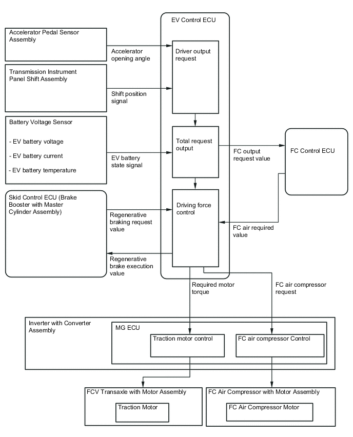
FC system output control
-
The EV control ECU uses the accelerator opening angle, shift position signal and vehicle speed signal to calculate the driver's requested output, and makes the total output request according to driving conditions, controlling the driving power by sending request signals to the relevant ECUs.
-
Based on the FC output request received from the EV control ECU, the FC control ECU determines the necessary air and hydrogen amounts. The FC control ECU controls the injector of the FC stack assembly and the hydrogen pump to acquire the hydrogen needed for electrical generation and at the same time sends a request for the necessary air amount to the EV control ECU in the form of a requested RPM value for the FC air compressor.
-
Based on the torque request from the EV control ECU, the MG ECU controls the FC compressor and the driving force of the traction motor.
-
In certain situations, the FC system will judge the vehicle conditions and perform output restriction. While output restriction is in effect, the intended level of vehicle acceleration might not be obtainable.
-
Output restriction due to FC control system temperature increase (restriction by EV control ECU and FC control ECU)
When continuously driving uphill or driving at a high output level at high altitude has caused the temperature of the FC cooling system to increase, the electrical power supplied to the traction motor will be restricted, and a message will be displayed in the multi-information display of the combination meter informing that output has been restricted due to high temperature of the FC cooling system. When the temperature of the FC cooling system returns to the normal range, the restriction will be cancelled.
-
Output restriction due to inverter and the traction motor temperature increase (restriction by EV control ECU)
When driving at a high load level has caused the temperature of the traction system cooling system to increase, the electrical power supplied to the traction motor will be restricted, and a message will be displayed in the multi-information display of the combination meter informing that output has been restricted due to high temperature of the inverter and the traction motor. When the temperature of the inverter and the traction motor returns to the normal range, the restriction will be cancelled.
-
Output restriction when starting at freezing temperatures (restriction by FC control ECU)
When the system is started at temperatures below freezing, the fuel cell performance is reduced. As the FC stack coolant temperature increases, the output restriction is gradually removed.
-
Output restriction due to low fuel remaining (restriction by FC control ECU)
When the amount of hydrogen fuel remaining in the hydrogen tank has decreased to the specified value (6%) or less, a message will be displayed informing that output is restricted due to low fuel remaining. If the vehicle continues to be driven, when the remaining hydrogen fuel pressure is 1MPa or less, the FC control system will stop and electrical generation will stop. If the SOC of the EV battery is low, the vehicle will also stop.
-
Output restriction due to FC air compressor with motor assembly temperature (restriction by FC control ECU)
If the temperature of the built-in motor of the FC air compressor with motor assembly has increased, or if the compressor portion temperature has decreased, output will be restricted to protect the FC air compressor with motor assembly.
-
When repeated accelerations and decelerations have been performed continuously, the EV battery is being subjected to abrupt charging and discharging, which can result in temperature increases or reductions of the SOC, causing reduced power output. Also, in a low temperature environment, output will also be reduced if the EV battery temperature is low.
-
-
-
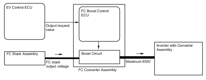
FC stack electrical power and boost restrictions
-
Based on requests from the EV control ECU, the FC boost control ECU built into the boost converter assembly controls the electrical output power of the FC stack assembly and at the same time boosts the voltage to a maximum of 650 V and supplies it to the inverter with converter assembly.
-
According to the current command value requested by the EV control ECU, the FC boost converter operates one phase only when at low load, and activates additional phases as necessary so that at medium to high loads the number of phases increases to 2, 3, and 4 phases. This minimizes IGBT switching losses in order to improve fuel efficiency.
-
-
Electronically controlled brake control
-
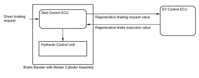
Electronically controlled hydraulic brake control and cooperative control
-
The electronically controlled hydraulic brake system uses communication between the EV control ECU and the skid control ECU to cooperatively control the regenerative braking force from the traction motor and the braking force from the hydraulic brake in order to perform regenerative cooperative brake control that can effectively reuse the driving energy.
-
The skid control ECU detects the driver's brake operation amount, and sends the calculated regenerative brake braking force request value to the EV control ECU. Based on the requested value, the EV control ECU performs regenerative brake control, and at the same time sends the actual regenerative brake control value to the skid control ECU.
-
-
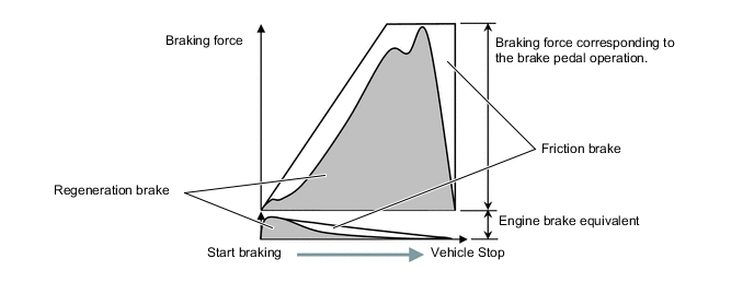
Regenerative brake control
-
The electrical energy from the regenerative braking is used to charge the EV battery, or is discharged and consumed by auxiliary equipment such as the FC air compressor.
-
-
-
Control in a collision
-
When the vehicle has received a strong impact and an airbag operation signal has been received from the airbag ECU assembly, the FC system turns off the hydrogen tank shut valve relay to shut off the flow of hydrogen fuel, and at the same time turns off the SMR (system main relay) and FC main relay, shutting off the high voltage power supply circuits to ensure safety.
-
-
Drive Start Control System
-
When abnormal driver accelerator pedal and shift operations are detected, the system limits the motive force and informs the driver.
Tech Tips
When the system is operating, even if the driver depresses and holds the accelerator pedal, motive force may increase on an uphill slope and decrease on a downhill slope. This behavior allows the system to restrict the vehicle speed and acceleration below the predetermined limit on slopes and is not a malfunction.
-
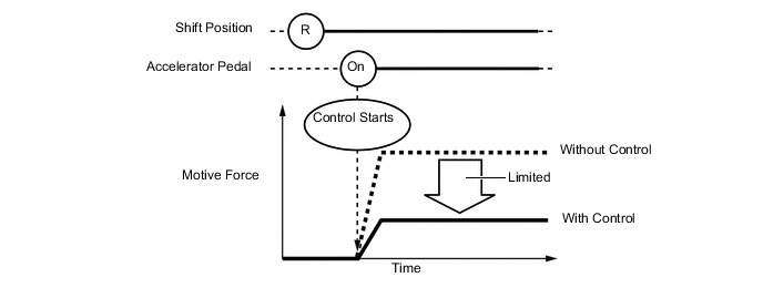
Control during Reverse Operation
-
Responds to excessive depression of the accelerator pedal while operating in reverse.
-
Corrects motive force according to the road grade and steering angle.
Control Start Conditions
(When all of the following conditions are met, control starts.)
-
Shift position is R.
-
Accelerator pedal is depressed.
Control Operation Limits the motive force so the vehicle speed and acceleration are at or below a certain level. Control Stop Conditions
-
Shift position is not R.
-
Accelerator pedal is fully released.
-
-
-
Control during Manual Shift Operation
-
Responds to shift operations with the accelerator pedal depressed.
-
Changes the limit amount according to the manual shift operation pattern.
-
Corrects motive force according to the road grade and steering angle.
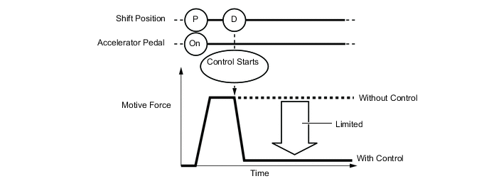
Control when Starting Off from a Parked Position Control Start Conditions
(When all of the following conditions are met, control starts.)
-
Shift position is changed from P to D, or P to R.
-
Accelerator opening angle is approximately 1/5 or higher.
Control Operation Limits the motive force so the vehicle speed and acceleration are at or below a certain level. Control Stop Conditions
-
Shift position is not P or N.
-
Accelerator pedal is fully released.
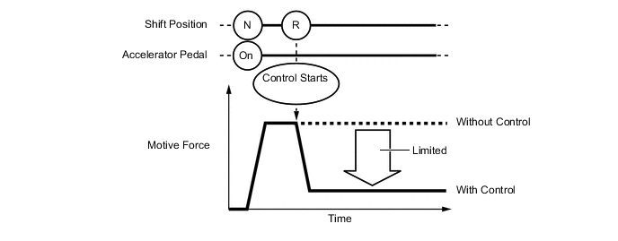
Figure 2. Image of control during other situations
Control during Other Situations Control Start Conditions
(When all of the following conditions are met, control starts.)
-
Shift position is changed from R to D, or D to R, or N to R
-
Accelerator opening angle is approximately 1/5 or higher.
Control Operation Limits the motive force so the vehicle speed and acceleration are at or below a certain level. Control Stop Conditions
-
Shift position is not P or N.
-
Accelerator pedal is fully released.
CAUTION:
-
The motive force restraint level differs in the above 2 situations
-
During control while a manual shift operation is performed (from control start until the accelerator pedal is released), the system informs the driver of the control via the multi-information display.
-
-
-
-
FUNCTION
-
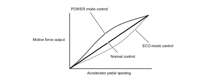
Driving mode
-
By selecting a driving mode, the FC system output characteristics in response to accelerator opening angle can be changed.
-
Selecting the ECO mode switch or POWER mode switch will activate the respective driving mode. If neither switch is selected, the vehicle is in Normal mode.

*1 Integration Control and Panel Assembly - - *a ECO Mode Switch *b POWER Mode Switch Figure 3. Motive Force Output Characteristics
-
When driving without depressing the accelerator pedal, operating the shift lever to Br mode will activate both the regenerative and hydraulic brakes, generating stronger deceleration force than when in the D position. Depressing the accelerator pedal or operating the shift lever to the D position will return to normal driving mode.
-
To display the driving mode selection status, driving mode indicator lights are provided in the combination meter assembly.
Mode Characteristics Driving Mode Control Characteristics Normal Mode Control is optimized for ease of driving. ECO Mode The amount of driving force generated in response to accelerator pedal angle is controlled for a milder response, and air conditioner control is changed to give priority to fuel efficiency, with the overall control objective of more fuel-efficient driving. POWER Mode At intermediate accelerator opening angles, the power output response is greater than in normal mode, improving accelerator responsiveness. Br Mode The regenerative brakes and hydraulic brakes are operated to generate stronger deceleration than when in the D position.
-
-