AUTOMATIC TRANSMISSION SYSTEM
-
FUNCTION OF MAIN COMPONENTS
Component Function Torque Converter Assembly
-
Transmits the engine power to the transmission.
-
Increases engine torque.
Oil Pump Provides oil pressure necessary for transmission operation. No. 1 Clutch (C1) Connects the input shaft and the intermediate shaft. No. 2 Clutch (C2) Connects the input shaft and the center planetary carrier. No. 3 Clutch (C3) Connects the input shaft and the front sun gear. No. 1 Brake (B1) Prevents the front planetary carrier from turning either clockwise or counterclockwise. No. 2 Brake (B2) Prevents the front and center planetary ring gears from turning either clockwise or counterclockwise. No. 3 Brake (B3) Prevents the outer race of No. 2 1-way clutch (F2) from turning either clockwise or counterclockwise. No. 4 Brake (B4) Prevents the center planetary carrier and the rear planetary ring gear from turning either clockwise or counterclockwise. No. 1 1-way Clutch (F1) Prevents the front planetary carrier from turning counterclockwise. No. 2 1-way Clutch (F2) Prevents the front planetary sun gear from turning counterclockwise when No. 3 brake (B3) is operating. No. 3 1-way Clutch (F3) Prevents the center planetary carrier and the rear planetary ring gear from turning counterclockwise. Planetary Gears Change the route through which driving force is transmitted, in accordance with the operation of each clutch and brake, in order to increase or reduce the input and output speed. Solenoid Valve (S1) Switches the 2-3 shift valve. Solenoid Valve (S2) Switches the 1-2 shift valve or 3-4 shift valve. Solenoid Valve (SR) Switches the clutch apply control valve. Solenoid Valve (SL1)
-
Controls clutch pressure.
-
Controls accumulator back pressure.
Solenoid Valve (SL2) Controls brake pressure. Solenoid Valve (SLT)
-
Controls line pressure.
-
Controls accumulator back pressure.
Solenoid Valve (SLU)
-
Controls lock-up clutch pressure.
-
Controls accumulator back pressure.
No. 1 ATF Temperature Sensor Detects the ATF temperature. No. 2 ATF Temperature Sensor Detects the ATF temperature. Transmission Revolution Sensor (NT) Detects the input speed of the transmission. Transmission Revolution Sensor (SP2) Detects the output speed of the transmission. Park/Neutral Position Switch Assembly Detects the shift lever position (P, R, N, D). Shift Paddle Switch (Transmission ShiftSwitch Assembly) Detects the driver's upshift or downshift request. Transmission Floor Shift Assembly Transmission Control Switch
-
Detects that the shift lever is in S.
-
Detects the driver's upshift and downshift operations when the shift lever is in S.
Transfer Shift Actuator Assembly L4 Detection Switch Detects that the transfer shift position is L4. Combination Meter Assembly Multi-information Display
-
Displays the shift lever position.
-
Displays the shift range.
-
Displays a message when the ATF is at a high temperature.
MIL Illuminates or blinks to inform the driver when the ECM detects a malfunction. Multi Buzzer Sounds when downshift operation is rejected in S mode. 4 Wheel Drive Control ECU Sends a transfer shift position signal to inform the ECM. Air Conditioning Amplifier Assembly* Sends a shift-up tardiness control signal to the ECM. ECM Controls engine output in response to a signal from the TCM. TCM
-
Controls each shift solenoid valve in response to a signal from each sensor and switch.
-
Makes a diagnosis and memorizes the failed section when the TCM detects a malfunction.
*: Models with automatic air conditioning system
-
-
SYSTEM CONTROL
Electronic Control of Automatic Transmission Control Outline Shift Timing Control The TCM sends current to solenoid valves (S1), (S2) and/or (SR) based on signals from various sensors in order to shift the gears. Line Pressure Control Actuates the solenoid valve (SLT) to control the line pressure in accordance with information from the TCM and the operating conditions of the transmission. Clutch Pressure Optimal Control The solenoid valves (SL1) and (SLT) minutely control the clutch pressure in accordance with the engine output and driving conditions of the transmission. Clutch to Clutch Pressure Control Controls the pressure that is applied directly to No. 1 brake (B1) and No. 1 clutch (C1) by actuating the solenoid valves (SL1) and (SL2) in accordance with the TCM signals. Engine Torque Control Reduces the fuel injection volume temporarily to improve shift feeling when upshifts or downshifts occur. N to D Squat Control When the shift lever is moved from N to D, the gear is temporarily engaged to the 2nd and then to the 1st to reduce vehicle squat. Lock-up Timing Control The TCM sends current to the solenoid valve (SLU) based on signals from various sensors and engages or disengages the lock-up clutch. Multi-mode Automatic Transmission
-
The ECM appropriately controls the automatic transmission in accordance with the shift range position selected using the shift lever or shift paddle switch (transmission shift switch assembly) while the shift lever is in S.
-
When the shift lever is in D, the driver can select a desired shift range using the shift paddle switch (transmission shift switch assembly).
ATF High Temperature Control When the ATF is at a high temperature, normal shifting characteristics will be changed to shifting characteristics which actively utilize the low gear range to prevent the oil temperature from rising further.
-
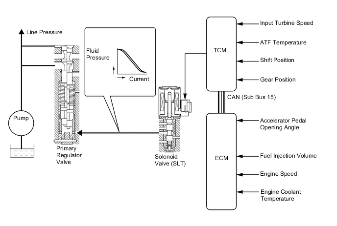
Line Pressure Control
-
In order to obtain a predetermined line pressure characteristic in accordance with each sensor signal, the TCM activates the solenoid valve (SLT) to regulate the throttle pressure.
-
This makes it possible for the primary regulator valve to precisely and minutely control the line pressure in accordance with the engine output, thus providing smoother shift characteristics.
-
-
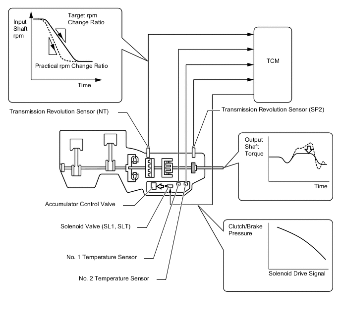
Clutch Pressure Optimal Control
-
The TCM monitors the signals from various types of sensors, such as the transmission revolution sensor (NT), allowing solenoid valves (SL1) and (SLT) to minutely control the clutch pressure in accordance with engine output and driving conditions. As a result, smooth shift characteristics are achieved.
-
-
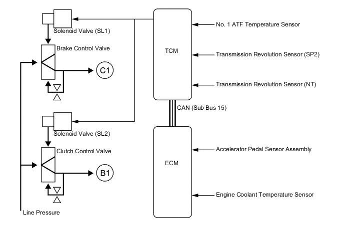
Clutch to Clutch Pressure Control
-
This control is used for shifting from 4th to 5th gear and from 5th to 4th gear.
-
The TCM actuates solenoid valves (SL1) and (SL2) in accordance with various signals. The output from these solenoid valves acts directly on control valves B1 and C1 in order to regulate the line pressure that acts on the No. 1 brake (B1) and No. 1 clutch (C1).
-
As a result, high response and excellent shift characteristics have been achieved.
-
-
Lock-up Timing Control
-
The TCM operates the lock-up timing control in order to improve fuel economy.
Lock-up Timing Control Operation Gear Position Shift Lever Position or Shift Range D, S5 S4 1st X X 2nd X X 3rd X X 4th X ○ 5th ○ - Tech Tips
○ : Available
X : Does not operate
- : Not applicable
-
-
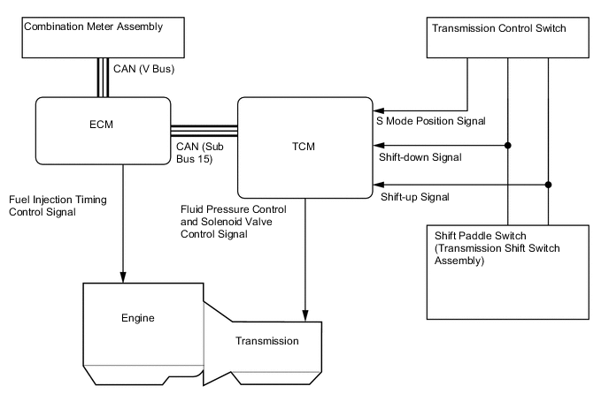
Multi-mode Automatic Transmission
-
The driver can select the desired gear step by moving the shift lever "+" (forward) or to "-" (backward) while the shift lever is in S (5-speed sequential shiftmatic mode). Also, the shift paddle switch (transmission shift switch assembly) can be used to change the gear steps while the driver is holding the steering wheel. Thus, the driver is able to change gear steps with a manual-like feel.
-
5-speed sequential shiftmatic mode can be selected from normal driving mode by moving the shift lever to S. The driver can change the gear step by selecting it using the shift lever.
-
The driver selects S mode by moving the shift lever to S. At this time, the S4 or S5 range is selected in accordance with the vehicle speed.
-
When the shift lever is in D, the driver can momentarily select a desired gear steps by operating the shift paddle switch (transmission shift switch assembly). Automatic shifting will be reinstated under the following conditions:
-
The vehicle has stopped.
-
The driver continues to push the shift paddle switch (transmission shift switch assembly) in the "+" direction longer than 1 second.
-
The driver depresses the accelerator pedal longer than a predetermined length of time (only when the shift range is 4th or 5th).
-
-
The TCM will restrict the changing of the shift range if it detects a malfunction in the automatic transmission system.
-
If the vehicle speed and engine speed exceed or go below a preset level in response to the driver's downshift operation request, changing the shift range will be prohibited. In this case, the buzzer in the combination meter will sound to alert the driver.
-
The shift lever position and the shift range are indicated by the multi-information display in the combination meter assembly.
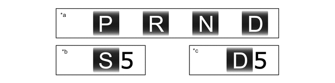
*a When Shift Lever is in P, R, N or D *b When Shift Lever is in S *c When Shift Paddle Switch (Transmission Shift Switch Assembly) is Operated with Shift Lever is in D - -
-
-
-
FAIL-SAFE
-
The fail-safe function minimizes the loss of operability when an abnormality occurs in a sensor or a solenoid valve.
-
For details, refer to the Repair Manual.
-
-
DIAGNOSIS
-
When the TCM detects a malfunction, it makes a diagnosis and memorizes the failed section. Furthermore, the TCM illuminates or blinks the MIL in the combination meter assembly to inform the driver.
-
The TCM will also store the Diagnostic Trouble Codes (DTCs) of the malfunctions. The DTCs can be read by connecting a Global TechStream (GTS) to the DLC3.
-
For details, refer to the Repair Manual.
-