EMISSION CONTROL SYSTEM
-
CONSTRUCTION
-
Models with EGR Cooler
-
A water-cooled type No. 1 EGR cooler is used between the exhaust manifold and electric EGR control valve assembly. In the water-cooled type No. 1 EGR cooler, engine coolant flows through eight-layered gas passage to cool down the EGR gas.
-
The No. 2 EGR valve assembly is used. The EGR gas passage is switched in 2 stages by the No. 2 EGR valve assembly to optimize the temperature of the EGR gas.
Figure 1. EGR Gas Flow
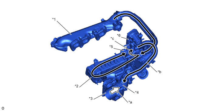
*1 Exhaust Manifold *2 No. 1 EGR Cooler *3 Diesel Throttle Body Assembly *4 Intake Manifold *5 No. 2 EGR Valve Assembly *6 Electric EGR Control Valve Assembly *a Intake Air *b EGR Gas *c EGR Gas (through Bypass Passage) - -
-
-
Models without EGR Cooler
-
EGR gas is sent to the intake manifold through the No. 1 EGR pipe, EGR valve adapter, EGR valve and No. 2 EGR pipe.
Figure 2. EGR Gas Flow
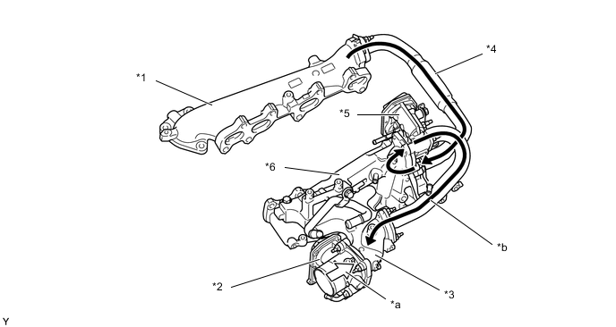
*1 Exhaust Manifold *2 Diesel Throttle Body Assembly *3 Intake Manifold *4 No. 1 EGR Pipe Sub-assembly *5 Electric EGR Control Valve Assembly *6 EGR Valve Adapter *a Intake Air *b EGR Gas
-
-