ENGINE UNIT
-
CONSTRUCTION
-
Each VVT-i controller consists of the housing driven from the timing chain and the vane coupled with the intake or exhaust camshaft.
-
The oil pressure sent from the advanced or retarded side path at the intake and exhaust camshafts causes rotation in the VVT-i controller vane circumferential direction to vary the intake and exhaust valve timing continuously.
-
The intake side has a 3-blade vane and the exhaust side has a 4-blade vane.
-
When the engine is stopped, the intake camshaft will be in the most retarded state and the exhaust camshaft will be in the most advanced state to ensure startability.
-
An advance assist spring is provided on the exhaust VVT-i controller. This spring applies torque in the advance direction when the engine is stopped, thus ensuring the engagement of the lock pin.
-
When hydraulic pressure is not applied to the VVT-i controller immediately after the engine has started, the lock pin locks the movement of the VVT-i controller to prevent a knocking noise. Thereafter, when hydraulic pressure is applied to the VVT-i controller, the lock pin is released.
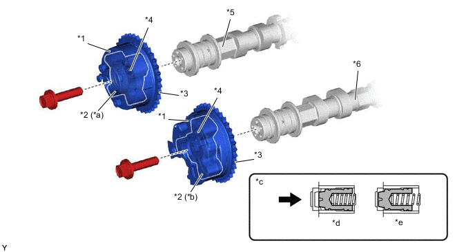
*1 Outer Housing *2 Vane *3 Timing Chain Sprocket *4 Lock Pin *5 Exhaust Camshaft (No. 2 Camshaft) *6 Intake Camshaft (Camshaft) *a Fixed on Exhaust Camshaft *b Fixed on Intake Camshaft *c Lock Pin Condition *d Engine Operating *e Engine Stopped - - 
Oil Pressure - -
-
-
OPERATION
-
Advance
-
When the camshaft timing oil control valve is positioned as illustrated below by the advance signals from the ECM, the resultant oil pressure is applied to the timing advance side vane chamber to rotate the camshaft in the timing advance direction:
Figure 1. Advance Side Operation
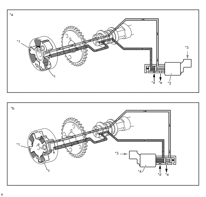
*1 Vane *2 Camshaft Timing Oil Control Valve Assembly (Intake) *3 ECM *4 Camshaft Timing Oil Control Valve Assembly (Exhaust) *a Intake Side *b Exhaust Side *c Advance Side Vane Chamber *d In *e Drain - - Oil Pressure 
Rotation Direction
-
-
Retard
-
When the camshaft timing oil control valve is positioned as illustrated below by the retard signals from the ECM, the resultant oil pressure is applied to the timing retard side vane chamber to rotate the camshaft in the timing retard direction:
Figure 2. Retard Side Operation
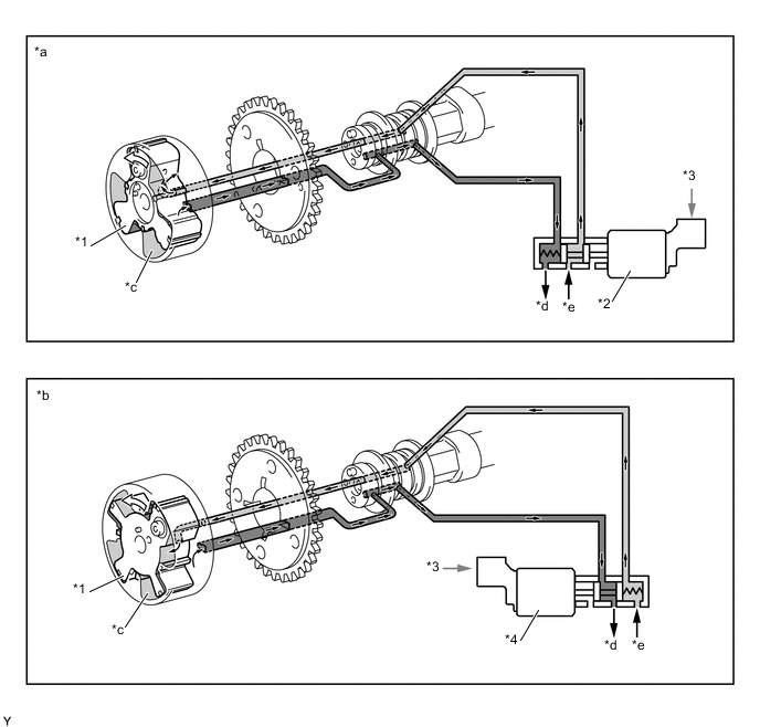
*1 Vane *2 Camshaft Timing Oil Control Valve Assembly (Intake) *3 ECM *4 Camshaft Timing Oil Control Valve Assembly (Exhaust) *a Intake Side *b Exhaust Side *c Advance Side Vane Chamber *d In *e Drain - - Oil Pressure Rotation Direction
-
-
Hold
-
After reaching the target timing, the valve timing is held by keeping the camshaft timing oil control valve in the neutral position unless the traveling state changes. This adjusts the valve timing at the desired target position and prevents the engine oil from running out when it is unnecessary.
-
-