SFI SYSTEM
-
FUNCTION
-
The ACIS uses a bulkhead to divide the intake manifold into 2 stages, with an intake air control valve in the bulkhead being opened and closed to vary the effective length of the intake manifold in accordance with the engine speed and throttle valve opening angle. This increases the power output in all ranges from low to high speed.
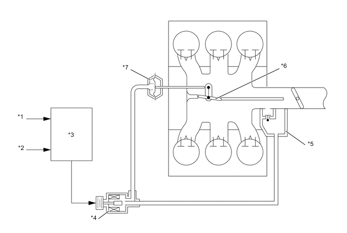
*1 Crank Position Sensor *2 Throttle Position Sensor *3 ECM *4 Vacuum Switching Valve Assembly (for ACIS) *5 Vacuum Tank *6 Intake Air Control Valve *7 Actuator - - -
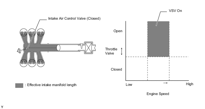
When Intake Control Valve Closes (VSV On)
-
The ECM activates the VSV to match the longer pulsation cycle so that the negative pressure acts on the diaphragm chamber of the actuator. This closes the control valve. As a result, the effective length of the intake manifold is lengthened and the intake efficiency in the medium speed range is improved due to the dynamic effect of the intake air, thereby increasing the power output.
Figure 1. When Intake Air Control Valve Closes
-
-
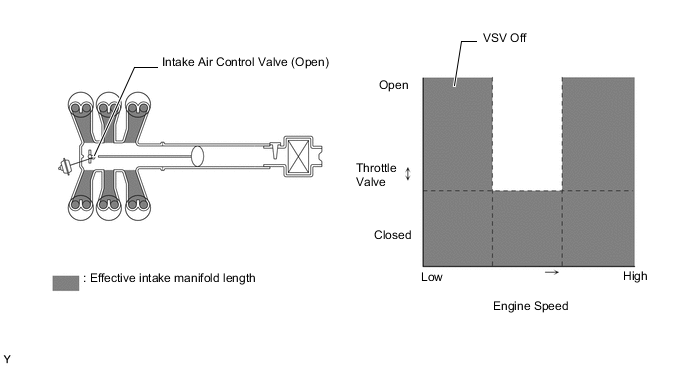
When the Intake Control Valve Opens (VSV Off)
-
The ECM deactivates the VSV to match the shorter pulsation cycle so that atmospheric air is led into the diaphragm chamber of the actuator and opens the control valve. When the control valve is open, the effective length of the intake air chamber is shortened and peak intake efficiency is shifted to the low-to-high engine speed range, thus providing greater output at low-to-high engine speeds.
Figure 2. When Intake Air Control Valve Opens
-
-