AIR CONDITIONING SYSTEM
-
CONSTRUCTION
-
The air conditioning unit consists of the No. 1 cooler evaporator sub-assembly, heater radiator unit sub-assembly, damper servo motors, No. 1 cooler thermistor (evaporator temperature sensor) and blower motor with fan sub-assembly.
-
The No. 1 cooler evaporator sub-assembly and heater radiator unit sub-assembly are mounted transversely to achieve a compact and lightweight form.
-
A bus connector is used in the wire harness connection, which connects the servo motor to the air conditioning amplifier assembly.*
-
Sliding doors are used for the air mix control doors, thus making the air conditioning radiator assembly more compact.
-
*: Models with automatic air conditioning system
Figure 1. Air Conditioning Unit Layout Parts Location
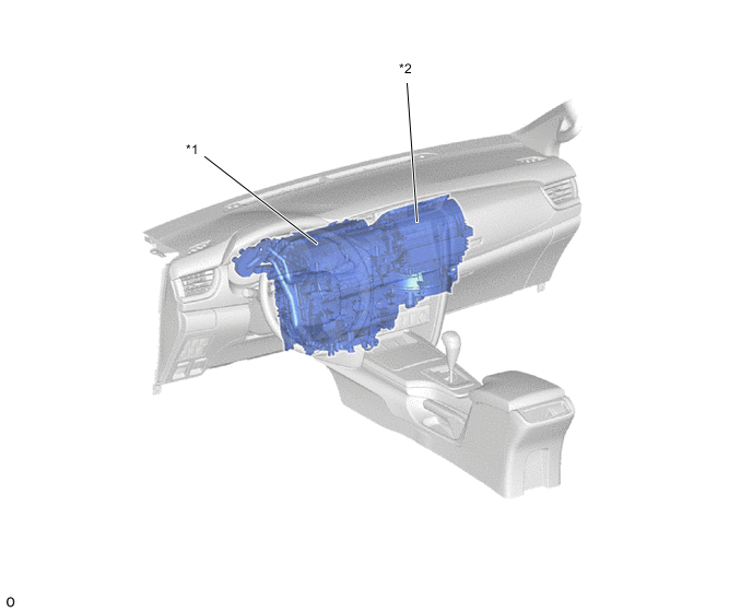
*1 Heater Radiator Unit Assembly *2 Blower Assembly -
-
Depending on the model, a cool air duct with a shutter is provided to the upper glove box side area of the front passenger side side register duct. The upper glove box can be used as a cool box by opening the shutter while the cooler is operating.
Figure 2. Duct Layout Parts Location
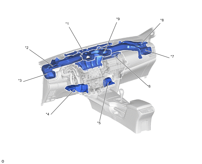
*1 Front Defroster Duct *2 Side Defroster Duct (LH) *3 Side Register Duct (LH) *4 Footwell Duct (LH) *5 Footwell Duct (RH) *6 Air Inlet Duct *7 Side Register Duct (RH) *8 Side Defroster Duct (RH) *9 Center Register Duct - -
-
-
OPERATION
-
Mode Position and Damper Operation
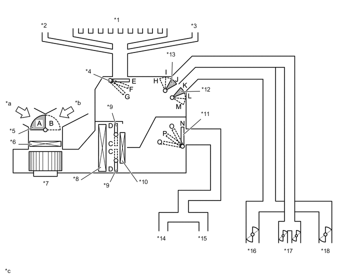
*1 Front Defroster *2 Side Defroster (LH) *3 Side Defroster (RH) *4 Mode Switching Damper (for Defroster) *5 Fresh/Recirculation Damper *6 Clean Air Filter (Air Refiner Element) *7 Blower Motor with Fan Sub-assembly *8 No. 1 Cooler Evaporator *9 Air Mix Damper *10 Heater Radiator Unit Sub-assembly *11 Mode Switching Damper (for Footwell Duct) *12 Mode Switching Damper (for Side Register) *13 Mode Switching Damper (for Center Register) *14 Footwell Duct (LH) *15 Footwell Duct (RH) *16 Side Register (LH) *17 Center Register *18 Side Register (RH) *a Recirculated Air *b Fresh Air *c This illustration shows the dampers and air outlets schematically. It will differ from the actual. - - Mode Position and Damper Operation Chart Damper Operation Position Damper Position Operation Air Inlet Control Damper FRESH A Brings in fresh air. RECIRC B Recirculates internal air. Air Mix Control Damper HI - LO C - D Varies the mixture ratio of cool air and hot air in order to regulate the temperature continuously from HI to LO. Mode Control Damper FACE E, H, M, N Air blows out of the center register and side register. BI-LEVEL E, I, L, P Air blows out of the center register, side register and footwell register. FOOT F, J, L, Q Air blows out of the footwell register duct. A small amount of air also blows out from the side register, front defroster and side defroster. FOOT/DEF G, J, L, O Defrosts the windshield through the front defroster and side defroster. At the same time, air is blown out from the footwell register. A small amount of air also blows out from the side register. DEF G, J, L, N Defrosts the windshield through the front defroster and side defroster. A small amount of air also blows out from the side register. -
Air Outlets and Airflow Volume
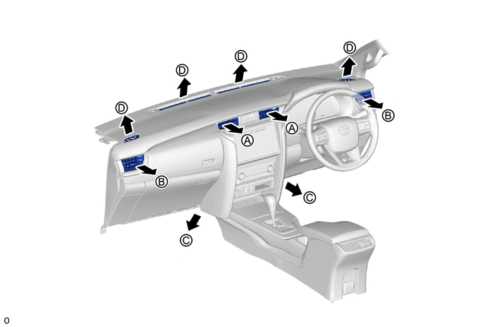
Indication Mode Center Register Side Register Footwell Duct Front Defroster, Side Defroster A B C D 
FACE 
- - 
BI-LEVEL 
- 
FOOT - 

FOOT/DEF - 
DEF - -
-