AIR CONDITIONING SYSTEM
-
FUNCTION OF MAIN COMPONENTS
Front Automatic Air Conditioning System or Manual Air Conditioning System Component Function Air Conditioning Control Assembly Allows operation and adjustment of the air conditioning system via switches.*1 Sends manual cooler operation signals to the air conditioning amplifier assembly.*2 Cooler Compressor Assembly Performs suction, compression and discharge of refrigerant gas. Blower Motor with Fan Sub-assembly Driven according to the target airflow volume calculated by the air conditioning amplifier assembly to blow air toward the cabin and circulate the air inside the cabin.*1 Driven according to the blower switch position to blow air toward the cabin and circulate the air inside the cabin.*2 Blower Motor Control*1 Controlled by the air conditioning amplifier assembly to control the blower motor with fan sub-assembly. Air Conditioning Amplifier Assembly Transmits and receives data to and from the switches and sensors, and controls the air conditioning system*1 or cooler system*2. ECM Receives the signals from the engine coolant temperature sensor and transmits them to the air conditioning amplifier assembly.*1 Receives the signals from the accelerator pedal position sensor and transmits the cooler compressor assembly off signal to the air conditioning amplifier assembly.*2 Cooler (Room Temp. Sensor) Thermistor*1 Detects the internal temperature inside the cabin and outputs that data to the air conditioning amplifier assembly. Thermistor Assembly (Ambient Temperature Sensor)*1 Detects ambient temperature and outputs it to the air conditioning amplifier assembly via the combination meter assembly. No. 1 Cooler Thermistor Detects the temperature of the cool air past the cooler evaporator sub-assembly and transmits the data to the air conditioning amplifier assembly. Cooler (Solar Sensor) Thermistor*1 Detects the changes in the amount of solar energy and outputs them to the air conditioning amplifier assembly. No. 1 Pressure Switch Detects the refrigerant pressure and sends the refrigerant pressure signal to the air conditioning amplifier assembly. Damper Servo Metors Controlled by the air conditioning amplifier assembly to move the mode control dampers*1, air mix control dampers*1 and fresh/recirculation damper and switch the registers, outlet air temperature and air inlet mode. PTC Heater (Quick Heater Assembly) Consists of Position Temperature Coefficient (PTC) element and an aluminum fin. *1: Models with automatic air conditioning system
*2: Models with manual air conditioning system
Rear Automatic Cooler System or Rear Manual Cooler System Component Function Integration Control and Panel Assembly*1
-
Sends auto switch signal to the air conditioning amplifier assembly.
-
Displays the blower level on the LCD.
Rear Cooler Switch*2 Operates the rear cooling unit (Blower motor with fan sub-assembly). Blower Motor with Fan Sub-assembly Driven according to the target airflow volume calculated by the air conditioning amplifier assembly to blow air toward the cabin and circulate the air inside the cabin.*1 Driven according to the rear cooler switch position to blow air toward the cabin and circulate the air inside the cabin.*2 Rear Blower Motor Control*1 Controled by the air conditioning amplifier assembly to control the blower motor with fan sub-assembly. Air Conditioning Amplifier Assembly*1 Transmits and receives data to and from the integration control and panel assembly, and controls the rear cooler system. *1: Models with rear automatic cooler system
*2: Models with rear manual cooler system
-
-
SYSTEM CONTROL
-
The automatic air conditioning system uses the following controls:
Control Outline Neural Network Control This control is capable of performing complex control by artificially simulating the information processing method of the nervous system of living organisms in order to establish a complex input/output relationship that is similar to that of a human brain. Front Outlet Air Temperature Control Based on the temperature set at the temperature control switch, the neural network control calculates the outlet air temperature based on the input signals from various sensors. Front Blower Control Controls the blower motor in accordance with the airflow volume that has been calculated by the neural network control based on the input signals from various sensors. Front Air Outlet Control Automatically switches the air outlets in accordance with the outlet mode that has been calculated by the neural network control based on the input signals from various sensors. Air Inlet Control Automatically controls the air inlet control damper to achieve the calculated outlet air temperature that is required. Drives the servo motor (for air inlet) in accordance with the operation of the air inlet control switch and moves the dampers to the FRESH or RECIRC position. Cooler Compressor Control Through the calculation of the target evaporator temperature based on various sensor signals, the air conditioning amplifier assembly controls the magnet clutch of the cooler compressor assembly. If the AUTO button is pressed, the air conditioning is automatically turned on when the blower is on and air conditioning is off. Eco Drive Mode Control On models with an ECO mode switch, when set to Eco drive mode, the air conditioning amplifier assembly decreases the blower speed. Diagnosis A Diagnostic Trouble Code (DTC) is stored in memory when the air conditioning amplifier assembly detects a problem with the air conditioning system. Rear Blower Control Controls the rear blower motor in accordance with the airflow volume that has been calculated by the neural network control based on the input signals from various sensors. -
Neural Network Control (Models with Automatic Air Conditioning System)
-
In previous automatic air conditioning systems, the air conditioning amplifier assembly determined the required outlet air temperature and blower air volume in accordance with the calculation formula obtained based on information received from the sensors. However, because the senses of a person are rather complex, a given temperature is sensed differently depending on the environment in which the person is situated. For example, a given amount of solar radiation can feel comfortably warm in a cold climate, or extremely uncomfortable in a hot climate. Therefore, as a technique for performing a higher level of control, a neural network is used in the automatic air conditioning system. With this technique, the data that has been collected under varying environmental conditions is stored in the air conditioning amplifier assembly. The air conditioning amplifier assembly can then perform control to provide enhanced air conditioning comfort.
-
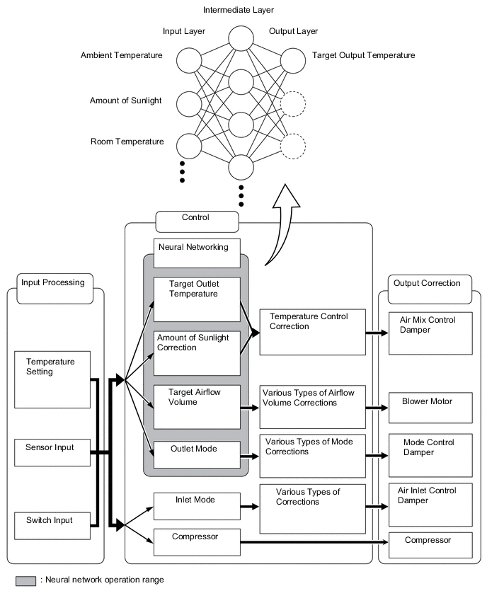
The neural network control consists of neurons in the input layer, intermediate layer and output layer. The input layer neurons process the input data of the outside temperature, the amount of sunlight and the room temperature based on the outputs of the switches and sensors, and output them to the intermediate layer neurons. Based on this data, the intermediate layer neurons adjust the strength of the links among the neurons. The sum of this data is then calculated by the output layer neurons in the form of the required outlet temperature, solar correction, target airflow volume and outlet mode control volume. Accordingly, the air conditioning amplifier assembly controls the servo motors and blower motor in accordance with the control volumes that have been calculated by the neural network control.
-
-
Eco Drive Mode Control (Models with Automatic Air Conditioning System)
-
Under the control of the Eco drive mode, the air conditioning amplifier assembly restricts the air conditioning system performance under specified conditions, thus improving fuel economy.
-
The Eco drive mode control is activated when the ECO mode switch is pushed, and then restricts the air conditioning system performance as described below:
Control Outline Inside/outside Air Switch Control Automatically switches the air inlet port to the internal air circulation mode when the outside air temperature is equal to or higher than a predetermined temperature and reduces the power consumption. Blower Level Control Sets the blower level in AUTO mode lower than normal, and suppresses power consumption.
-
-
-
DIAGNOSIS
-
Automatic Air Conditioning System
-
The air conditioning amplifier assembly has a self-diagnosis function. It stores any operation malfunctions in the air conditioning system in memory in the form of Diagnostic Trouble Codes (DTCs). For details, refer to the Repair Manual.
-
-