TOYOTA PARKING ASSIST-SENSOR SYSTEM
-
FUNCTION OF MAIN COMPONENTS
-
The components have the following functions:
Component Function No. 1 Ultrasonic Sensor Detects the distance between the vehicle and on obstacle. No. 1 Clearance Warning Buzzer Sounds to inform the driver according to the distance to the obstacle. Clearance Warning ECU Assembly
-
Judges the approximate distance between the vehicle and an obstacle based on signals from the No. 1 ultrasonic sensors.
-
Sounds the No. 1 clearance warning buzzer.
IPA Main Switch Assembly Operating this switch allows the operation of Toyota parking assist-sensor system to be enabled or disabled. Park/Neatral Position Switch Assembly*1 Transmits the shift position signal to the clearance warning ECU assembly. Back-up Light Switch Assembly*2 Transmits the on/off signal of the back-up light switch assembly to the clearance warning ECU assembly. *1: Models with automatic transmission
*2: Models with manual transmission
-
-
-
OPERATING CONDITION
-
The operating condition of each sensor differs according to its installed position as shown in the table below:
Installation Position Operating Condition Rear Center
-
Ignition switch is ON.
-
IPA main switch assembly is on.
-
Shift lever is in R.
-
-
-
SYSTEM CONTROL
-
No. 1 Clearance Warning Buzzer
-
The on and off times of the No. 1 clearance warning buzzer vary as shown in the table below, depending on the distance between the obstacle and the ultrasonic sensor:
Ultrasonic Sensor Obstacle Distance [mm (in.)] Off Time (ms) On Time (ms) Detection Level Longest 1500 +/- 150 to 600 +/- 60 (59.1 +/- 5.91 to 23.6 +/- 2.36) 500 +/- 50 200 +/- 20 Long 600 +/- 60 to 450 +/- 50 (23.6 +/- 2.36 to 17.7 +/- 1.97) 200 +/- 20 200 +/- 20 Middle 450 +/- 50 to 350 +/- 40 (17.7 +/- 1.97 to 13.8 +/- 1.57 ) 100 +/- 10 100 +/- 10 Short 350 +/- 40 or less (13.8 +/- 1.57 or less) 0 Continuous 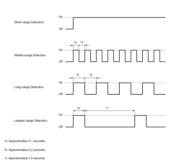
-
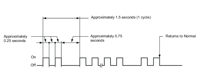
When a malfunction is detected, the No. 1 clearance warning buzzer continues to sound as shown in the illustration.
-
-
Detection Area
-
The detection areas of the No. 1 ultrasonic sensors are as shown in the following illustration.
-
These detection areas are applicable when positioning a 60 mm (2.36 in.) diameter pole parallel or perpendicular to the ground. The ranges vary depending on the measuring method and type of obstacle.
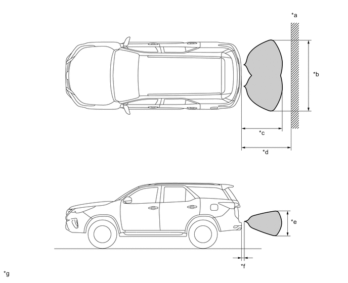
*a Wall *b Approximately 1720 mm (67.7 in.) *c Approximately 1000 mm (39.4 in.) *d Approximately 1500 mm (59.1 in.) *e Approximately 550 mm (21.6 in.) *f Approximately 100 mm (3.9 in.) *g The illustrations shown are examples only. - -
-
-