BRAKE CONTROL SYSTEM
-
CONSTRUCTION
-
The brake actuator assembly consists of an actuator portion and skid control ECU.

*1 Skid Control ECU *2 Actuator Portion -
The actuator portion consists of 2 master cylinder cut solenoid valves, 4 pressure holding solenoid valves, 4 pressure reduction solenoid valves, 2 pumps, 2 reservoirs and a master cylinder pressure sensor.
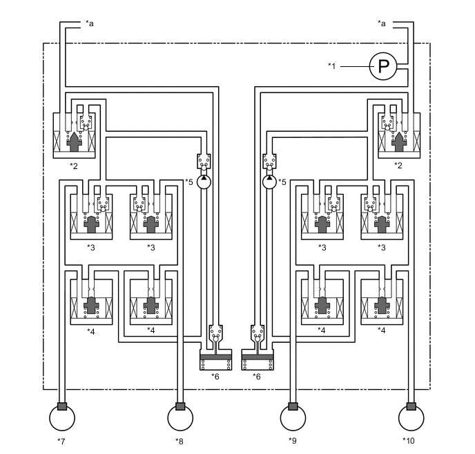
*1 Master Cylinder Pressure Sensor *2 Master Cylinder Cut Solenoid Valve *3 Pressure Holding Solenoid Valve *4 Pressure Reduction Solenoid Valve *5 Pump *6 Reservoir *7 Front Left Wheel Cylinder *8 Front Right Wheel Cylinder *9 Rear Left Wheel Cylinder *10 Rear Right Wheel Cylinder *a From Master Cylinder - -
-
-
OPERATION
-
ABS and EBD
-
Based on the signals received from the 4 speed sensors, the skid control ECU calculates the speed of each wheel and checks the wheel slipping conditions. In accordance with the slipping condition, the skid control ECU controls each solenoid valve in the brake actuator assembly in order to adjust the fluid pressure of each wheel cylinder in the following 3 modes: pressure increase, pressure holding and pressure reduction modes.
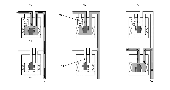
*1 Pressure Holding Solenoid Valve *2 Pressure Reduction Solenoid Valve *3 Port A *4 Port B *a Pressure Increase Mode *b Pressure Holding Mode *c Pressure Reduction Mode *d To Wheel Cylinder *e From Wheel Cylinder - - Brake Actuator Operation in ABS and EBD Pressure Mode Increase Mode Holding Mode Reduction Mode Pressure Holding Solenoid Valve (Port A) Off (Open) On (Closed) ← Pressure Reduction Solenoid Valve (Port B) Off (Closed) ← On (Open) Wheel Cylinder Pressure Increases Holds Reduces
-
-
Brake Assist
-
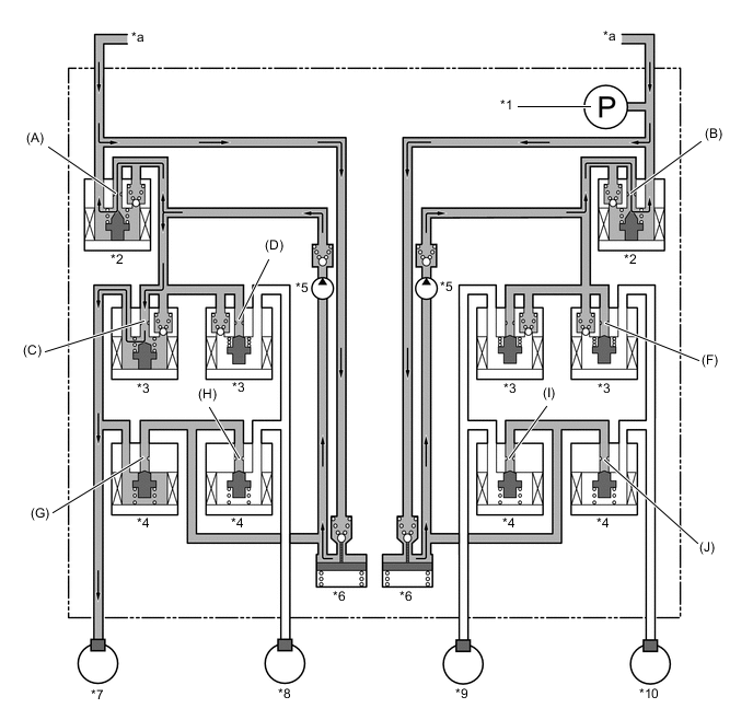
In the event of emergency braking, the skid control ECU determines the driver's intention based on the speed of the pressure increase in the master cylinder determined by the master cylinder pressure sensor signal. If the skid control ECU determines the need for additional brake assist, pressure is generated by the pump in the brake actuator assembly and directed to the wheel cylinder to apply a large amount of fluid pressure.
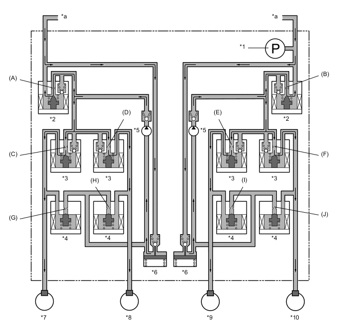
*1 Master Cylinder Pressure Sensor *2 Master Cylinder Cut Solenoid Valve *3 Pressure Holding Solenoid Valve *4 Pressure Reduction Solenoid Valve *5 Pump *6 Reservoir *7 Front Left Wheel Cylinder *8 Front Right Wheel Cylinder *9 Rear Left Wheel Cylinder *10 Rear Right Wheel Cylinder *a From Master Cylinder - - Brake Actuator Operation in Brake Assist Item Brake Assist not Activated Brake Assist Activated Pump Off On Master Cylinder Cut Solenoid Valve Port (A) Off (Open) On* Port (B) Off (Open) On* Pressure Holding Solenoid Valve Port (C) Off (Open) ← Port (D) Off (Open) ← Port (E) Off (Open) ← Port (F) Off (Open) ← Pressure Reduction Solenoid Valve Port (G) Off (Closed) ← Port (H) Off (Closed) ← Port (I) Off (Closed) ← Port (J) Off (Closed) ← Tech Tips
*: The solenoid valve switches the hydraulic pressure between "open" and "closed" in accordance with the operating conditions by adjusting continually.
-
-
TRC
-
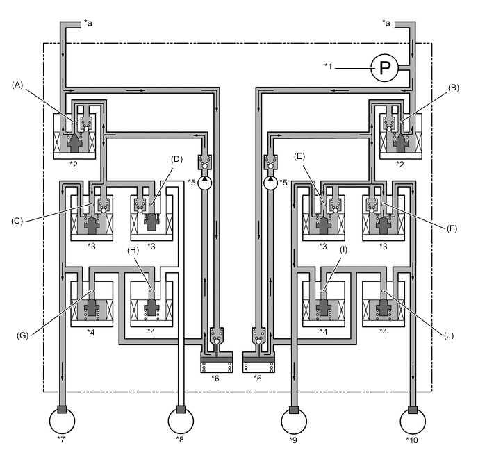
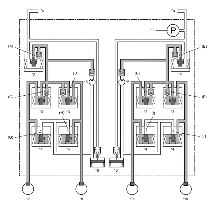
The fluid pressure generated by the pump is regulated by the master cylinder cut solenoid valve to the required pressure. Thus, the wheel cylinders of the drive wheels are controlled in the pressure increase, pressure holding and pressure reduction modes to control the slippage of the drive wheels. The pressure holding solenoid valve and the pressure reduction solenoid valve are turned on or off in accordance with ABS and EBD operation patterns.
*1 Master Cylinder Pressure Sensor *2 Master Cylinder Cut Solenoid Valve *3 Pressure Holding Solenoid Valve *4 Pressure Reduction Solenoid Valve *5 Pump *6 Reservoir *7 Front Left Wheel Cylinder *8 Front Right Wheel Cylinder *9 Rear Left Wheel Cylinder *10 Rear Right Wheel Cylinder *a From Master Cylinder - - Brake Actuator Operation in TRC*1 Item TRC Operation Not Activated Pressure Increase Mode Pressure Holding Mode Pressure Reduction Mode Pump Off On ← ← Master Cylinder Cut Solenoid Valve Port (A) Off (Open) On* ← ← Port (B) Off (Open) On* ← ← Front Brake Pressure Holding Solenoid Valve Port (C) Off (Open) ← On (Closed) ← Port (D) Off (Open) ← On (Closed) ← Pressure Reduction Solenoid Valve Port (G) Off (Closed) ← ← On (Open) Port (H) Off (Closed) ← ← On (Open) Wheel Cylinder Pressure Left - Increases Holds Reduces Right - Increases Holds Reduces Rear Brake Pressure Holding Solenoid Valve Port (E) Off (Open) ← On (Closed) ← Port (F) Off (Open) ← On (Closed) ← Pressure Reduction Solenoid Valve Port (I) Off (Closed) ← ← On (Open) Port (J) Off (Closed) ← ← On (Open) Wheel Cylinder Pressure Left - Increases Holds Reduces Right - Increases Holds Reduces Tech Tips
*: The solenoid valve switches the hydraulic pressure between "open" and "closed" in accordance with the operating conditions by adjusting continually.
-
-
A-TRC
-
Based on the vehicle speed that has been calculated from each speed sensor and the signals of the yawrate and deceleration sensor, the skid control ECU computes the target control speed.
-
The skid control ECU compares the target control speed and the wheel speed to determine whether or not slippage exists. Upon detecting slippage, the skid control ECU controls the solenoid valve of the brake actuator assembly to control the brake fluid pressure that is applied to the slipping wheel. When the wheel speed becomes lower than the target control speed, the skid control ECU stops increasing the brake fluid pressure.
-
The fluid pressure control of A-TRC independently controls the brake of each wheel by operating the individual solenoid valves in accordance with the signals received from the skid control ECU. The brake of each wheel is controlled in the following 3 modes: pressure increase, pressure holding, and pressure reduction modes.
*1 Master Cylinder Pressure Sensor *2 Master Cylinder Cut Solenoid Valve *3 Pressure Holding Solenoid Valve *4 Pressure Reduction Solenoid Valve *5 Pump *6 Reservoir *7 Front Left Wheel Cylinder *8 Front Right Wheel Cylinder *9 Rear Left Wheel Cylinder *10 Rear Right Wheel Cylinder *a From Master Cylinder - - Brake Actuator Operation in A-TRC Item A-TRC Operation Not Activated Pressure Increase Mode Pressure Holding Mode Pressure Reduction Mode Pump Off On ← ← Master Cylinder Cut Solenoid Valve Port (A) Off (Open) On* ← ← Port (B) Off (Open) On* ← ← Front Brake Pressure Holding Solenoid Valve Port (C) Off (Open) ← On (Closed) ← Port (D) Off (Open) ← On (Closed) ← Pressure Reduction Solenoid Valve Port (G) Off (Closed) ← ← On (Open) Port (H) Off (Closed) ← ← On (Open) Wheel Cylinder Pressure Left - Increases Holds Reduces Right - Increases Holds Reduces Rear Brake Pressure Holding Solenoid Valve Port (E) Off (Open) ← On (Closed) ← Port (F) Off (Open) ← On (Closed) ← Pressure Reduction Solenoid Valve Port (I) Off (Closed) ← ← On (Open) Port (J) Off (Closed) ← ← On (Open) Wheel Cylinder Pressure Left - Increases Holds Reduces Right - Increases Holds Reduces Tech Tips
*: The solenoid valve switches the hydraulic pressure between "open" and "closed" in accordance with the operating conditions by adjusting continually.
-
-
VSC
-
VSC, by way of the solenoid valves, controls the fluid pressure generated by the pump and applies it to the brake wheel cylinder of each wheel in the following 3 modes: pressure increase, pressure holding and pressure reduction modes. As a result, the tendency for front wheel skid or rear wheel skid is controlled.
-
In front wheel skid restraint control, the brakes of the front wheel on the outer circle of the turn and the rear wheels are applied. Also, depending on whether the brake is on or off and also depending on the vehicle condition, there are circumstances in which the brake might not be applied to the wheels even if the wheel is targeted for braking. The following diagram shows the hydraulic circuit in the pressure increase mode, as it controls the front wheel skid condition while the vehicle is making a right turn. In other operating modes, the pressure holding valve and the pressure reduction valve are turned on or off in accordance with ABS and EBD operation patterns.
*1 Master Cylinder Pressure Sensor *2 Master Cylinder Cut Solenoid Valve *3 Pressure Holding Solenoid Valve *4 Pressure Reduction Solenoid Valve *5 Pump *6 Reservoir *7 Front Left Wheel Cylinder *8 Front Right Wheel Cylinder *9 Rear Left Wheel Cylinder *10 Rear Right Wheel Cylinder *a From Master Cylinder - - Brake Actuator Operation in VSC (Front Wheel Skid Restraint when Making Right Turn) Item VSC Operation Not Activated Pressure Increase Mode Pressure Holding Mode Pressure Reduction Mode Pump Off On ← ← Master Cylinder Cut Solenoid Valve Port (A) Off (Open) On* ← ← Port (B) Off (Open) On* ← ← Front Brake Pressure Holding Solenoid Valve Port (C) Off (Open) ← On (Closed) ← Port (D) Off (Open) On (Closed) ← ← Pressure Reduction Solenoid Valve Port (G) Off (Closed) ← ← On (Open) Port (H) Off (Closed) ← ← ← Wheel Cylinder Pressure Left - Increases Holds Reduces Right - - - - Rear Brake Pressure Holding Solenoid Valve Port (E) Off (Open) ← On (Closed) ← Port (F) Off (Open) ← On (Closed) ← Pressure Reduction Solenoid Valve Port (I) Off (Closed) ← ← On (Open) Port (J) Off (Closed) ← ← On (Open) Wheel Cylinder Pressure Left - Increases Holds Reduces Right - Increases Holds Reduces Tech Tips
*: The solenoid valve switches the hydraulic pressure between "open" and "closed" in accordance with the operating conditions by adjusting continually.
-
In rear wheel skid restraint control, the brakes of the front wheel on the outer circle of the turn are applied. Also, depending on whether the brake is on or off and also depending on the vehicle condition, there are circumstances in which the brake might not be applied to the wheels even if the wheel is targeted for braking. The following diagram shows the hydraulic circuit in pressure increase mode, as it controls the rear wheel skid condition while the vehicle is making a right turn. In other operating modes, the pressure holding valve and the pressure reduction valve are turned on or off in accordance with ABS and EBD operation patterns.
*1 Master Cylinder Pressure Sensor *2 Master Cylinder Cut Solenoid Valve *3 Pressure Holding Solenoid Valve *4 Pressure Reduction Solenoid Valve *5 Pump *6 Reservoir *7 Front Left Wheel Cylinder *8 Front Right Wheel Cylinder *9 Rear Left Wheel Cylinder *10 Rear Right Wheel Cylinder *a From Master Cylinder - - Brake Actuator Operation in VSC (Rear Wheel Skid Restraint when Making Right Turn) Item VSC Operation Not Activated Pressure Increase Mode Pressure Holding Mode Pressure Reduction Mode Pump Off On ← ← Master Cylinder Cut Solenoid Valve Port (A) Off (Open) On* ← ← Port (B) Off (Open) On* ← ← Front Brake Pressure Holding Solenoid Valve Port (C) Off (Open) ← On (Closed) ← Port (D) Off (Open) On (Closed) ← ← Pressure Reduction Solenoid Valve Port (G) Off (Closed) ← ← On (Open) Port (H) Off (Closed) ← ← ← Wheel Cylinder Pressure Left - Increases Holds Reduces Right - - - - Rear Brake Pressure Holding Solenoid Valve Port (E) Off (Open) On (Closed) ← ← Port (F) Off (Open) On (Closed) ← ← Pressure Reduction Solenoid Valve Port (I) Off (Closed) ← ← ← Port (J) Off (Closed) ← ← ← Wheel Cylinder Pressure Right - - - - Left - - - - Tech Tips
*: The solenoid valve switches the hydraulic pressure between "open" and "closed" in accordance with the operating conditions by adjusting continually.
-
-
Hill-start Assist Control
-
Hill-start assist control operation is performed by closing the master cylinder cut solenoid valves after the driver operates the brake pedal and leaving a certain amount of hydraulic pressure created by the pump in the wheel cylinder. The diagram below shows the hydraulic circuit in the pressure holding mode.
*1 Master Cylinder Pressure Sensor *2 Master Cylinder Cut Solenoid Valve *3 Pressure Holding Solenoid Valve *4 Pressure Reduction Solenoid Valve *5 Pump *6 Reservoir *7 Front Left Wheel Cylinder *8 Front Right Wheel Cylinder *9 Rear Left Wheel Cylinder *10 Rear Right Wheel Cylinder *a From Master Cylinder - - Brake Actuator Operation in Hill-start Assist Control Item Hill-start Assist Control Operation Not Activated Pressure Holding Mode Pressure Reduction Mode Master Cylinder Cut Solenoid Valve Port (A) Off (Open) On* ← Port (B) Off (Open) On* ← Front Brake Pressure Holding Solenoid Valve Port (C) Off (Open) ← ← Port (D) Off (Open) ← ← Pressure Reduction Solenoid Valve Port (G) Off (Closed) ← On (Open) Port (H) Off (Closed) ← On (Open) Wheel Cylinder Pressure Left - Holds Reduces Right - Holds Reduces Rear Brake Pressure Holding Solenoid Valve Port (E) Off (Open) ← ← Port (F) Off (Open) ← ← Pressure Reduction Solenoid Valve Port (I) Off (Closed) ← On (Open) Port (J) Off (Closed) ← On (Open) Wheel Cylinder Pressure Left - Holds Reduces Right - Holds Reduces Tech Tips
*: The solenoid valve switches the hydraulic pressure between "open" and "closed" in accordance with the operating conditions by adjusting continually.
-
-
Downhill Assist Control
-
Based on the information provided by various sensors, switches and the ECM, the skid control ECU determines the conditions that enable downhill assist control operation. Then, the skid control ECU controls the fluid pressure that is generated by the pump and applies it by way of the solenoid valves to the brake wheel cylinder of each wheel in the following 3 modes: pressure reduction, pressure holding and pressure increase modes.
-
The skid control ECU computes the vehicle speed, travel direction and the gradient of the hill in accordance with the signals that are input by the speed sensor and the yawrate and deceleration sensor, and performs brake control to attain the target vehicle speed. The target vehicle speed is determined by the direction of the vehicle.
Travel Direction Target Vehicle Speed Forward 4 km/h to 8 km/h (2 mph to 5 mph) Backward 4 km/h to 7 km/h (2 mph to 4 mph) Tech Tips
When the transfer drive mode is in H4, and the accelerator pedal is depressed to increase the vehicle speed or the brake pedal is depressed to decrease the vehicle speed, the resulting vehicle speed becomes the target vehicle speed and control is performed to maintain that speed. Also, for models with a manual transmission, the engine may stall when the engine speed is low. Therefore, control is performed to increase the target vehicle speed and prevent the engine from stalling.
-
During downhill assist control operation, the skid control ECU outputs signals to the stop light switch assembly to cause the stop light to turn on, and to the combination meter assembly to cause the slip indicator light to blink.
*1 Master Cylinder Pressure Sensor *2 Master Cylinder Cut Solenoid Valve *3 Pressure Holding Solenoid Valve *4 Pressure Reduction Solenoid Valve *5 Pump *6 Reservoir *7 Front Left Wheel Cylinder *8 Front Right Wheel Cylinder *9 Rear Left Wheel Cylinder *10 Rear Right Wheel Cylinder *a From Master Cylinder - - Brake Actuator Operation in Downhill Assist Control Item Downhill Assist Control Operation Not Activated Pressure Increase Mode Pressure Holding Mode Pressure Reduction Mode Pump Off On ← ← Master Cylinder Cut Solenoid Valve Port (A) Off (Open) On* ← ← Port (B) Off (Open) On* ← ← Front Brake Pressure Holding Solenoid Valve Port (C) Off (Open) ← On (Closed) ← Port (D) Off (Open) ← On (Closed) ← Pressure Reduction Solenoid Valve Port (G) Off (Closed) ← ← On (Open) Port (H) Off (Closed) ← ← On (Open) Wheel Cylinder Pressure Left - Increases Holds Reduces Right - Increases Holds Reduces Rear Brake Pressure Holding Solenoid Valve Port (E) Off (Open) ← On (Closed) ← Port (F) Off (Open) ← On (Closed) ← Pressure Reduction Solenoid Valve Port (I) Off (Closed) ← ← On (Open) Port (J) Off (Closed) ← ← On (Open) Wheel Cylinder Pressure Left - Increases Holds Reduces Right - Increases Holds Reduces Tech Tips
*: The solenoid valve switches the hydraulic pressure between "open" and "closed" in accordance with the operating conditions by adjusting continually.
-
-