FOUR WHEEL DRIVE CONTROL SYSTEM
-
CONSTRUCTION
-
A planetary gear unit is used in the reduction mechanism and a silent chain is used for the front drive to reduce noise.
-
A synchromesh mechanism is used for the H2-H4 switching mechanism to achieve smooth engagement.
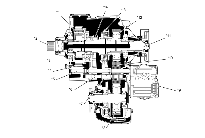
*1 Transfer Low Planetary Gear Assembly *2 Transfer Input Shaft *3 No. 2 Transfer Gear Shift Fork *4 Transfer Low Planetary Ring Gear *5 Fork Shaft *6 Transfer Front Drive Shift Fork Shaft *7 No. 1 Transfer Gear Shift Fork *8 Transfer Driven Sprocket *9 Transfer Shift Actuator Assembly *10 Transfer Front Drive Chain *11 Rear Transfer Output Shaft *12 Transfer Drive Sprocket Sub-assembly *13 Front Drive Clutch Sleeve *14 Transfer High and Low Clutch Sleeve
-
-
OPERATION
-
Transfer Mode H2 to H4
-
When the transfer position switch is turned from the H2 position to H4, this signal is input into the 4 wheel drive control ECU, and the 4 wheel drive control ECU activates the transfer shift actuator assembly.
-
The transfer shift motor moves the fork shaft to the right. At this time, the No. 1 transfer gear shift fork moves to the right together with the fork shaft.
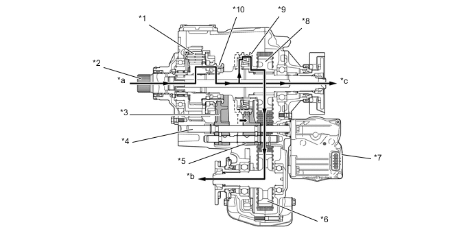
*1 Transfer Low Planetary Gear Assembly *2 Transfer Input Shaft *3 No. 2 Transfer Gear Shift Fork *4 Fork Shaft *5 No. 1 Transfer Gear Shift Fork *6 Transfer Driven Sprocket *7 Transfer Shift Actuator Assembly *8 Transfer Drive Sprocket Sub-assembly *9 Front Drive Clutch Sleeve *10 Transfer High and Low Clutch Sleeve *a From Transmission *b To Front Differential *c To Rear Differential - -
-
-
Transfer Mode H4 to H2
-
When the transfer position switch is turned from the H4 position to H2, this signal is input into the 4 wheel drive control ECU, and the 4 wheel drive control ECU actuates the transfer shift actuator assembly.
-
The transfer shift motor moves the fork shaft to the left. At this time, the No. 1 transfer gear shift fork moves to the left together with the fork shaft.
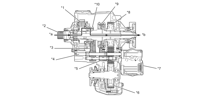
*1 Transfer Low Planetary Gear Assembly *2 Transfer Input Shaft *3 No. 2 Transfer Gear Shift Fork *4 Fork Shaft *5 No. 1 Transfer Gear Shift Fork *6 Transfer Driven Sprocket *7 Transfer Shift Actuator Assembly *8 Transfer Drive Sprocket Sub-assembly *9 Front Drive Clutch Sleeve *10 Transfer High and Low Clutch Sleeve *a From Transmission *b To Rear Differential
-
-
Transfer Mode H4 to L4
-
When the transfer position switch is turned from the H4 position to L4, this signal is input into the 4 wheel drive control ECU, and the 4 wheel drive control ECU actuates the transfer shift actuator assembly.
-
The transfer shift motor moves the fork shaft to the right. At this time, the No. 2 transfer gear shift fork moves to the right together with the fork shaft.
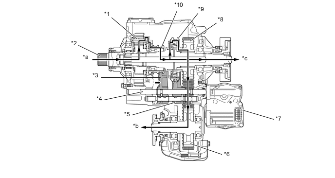
*1 Transfer Low Planetary Gear Assembly *2 Transfer Input Shaft *3 No. 2 Transfer Gear Shift Fork *4 Fork Shaft *5 No. 1 Transfer Gear Shift Fork *6 Transfer Driven Sprocket *7 Transfer Shift Actuator Assembly *8 Transfer Drive Sprocket Sub-assembly *9 Front Drive Clutch Sleeve *10 Transfer High and Low Clutch Sleeve *a From Transmission *b To Front Differential *c To Rear Differential - -
-
-
Transfer Mode L4 to H4
-
When the transfer position switch is turned from the L4 position to H4, this signal is input into the 4 wheel drive control ECU, and the 4 wheel drive control ECU actuates the transfer shift actuator assembly.
-
The transfer shift motor moves the fork shaft to the left. At this time, the No. 2 transfer gear shift fork moves to the left together with the fork shaft.

*1 Transfer Low Planetary Gear Assembly *2 Transfer Input Shaft *3 No. 2 Transfer Gear Shift Fork *4 Fork Shaft *5 No. 1 Transfer Gear Shift Fork *6 Transfer Driven Sprocket *7 Transfer Shift Actuator Assembly *8 Transfer Drive Sprocket Sub-assembly *9 Front Drive Clutch Sleeve *10 Transfer High and Low Clutch Sleeve *a From Transmission *b To Front Differential *c To Rear Differential - -
-
-
Transfer Mode L4 to H2
-
When the transfer position switch is turned from the L4 position to H2, this signal is input into the 4 wheel drive control ECU. Then, the 4 wheel drive control ECU actuates the transfer shift actuator assembly. The switching operation changes in the following sequence: L4 to H4, then H4 to H2.
-
-