FOUR WHEEL DRIVE CONTROL SYSTEM
-
FUNCTION OF MAIN COMPONENTS
Component Function Transfer Shift Actuator Assembly Transfer Shift Motor Switches the transfer shift position in accordance with signals from the 4 wheel drive control ECU. Limit Switch (TL1, TL2, TL3) Detects the position of the transfer shift motor and transmits a signal to the 4 wheel drive control ECU. 4WD Detection Switch Detects the H4 position of the transfer shift position and transmits a signal to the 4 wheel drive control ECU. L4 Detection Switch Detects the L4 position of the transfer shift position and transmits a signal to the 4 wheel drive control ECU. A.D.D. Actuator (Differential Motor Actuator Assembly) A.D.D. Shift Motor Connects or disconnects the differential side gear inter shaft sub-assembly and differential side gear shaft sub-assembly according to signals from the 4 wheel drive control ECU. Limit Switch (DL1, DL2) Detects the position of the A.D.D. shift motor and transmits a signal to the 4 wheel drive control ECU. A.D.D. Position Switch Detects the A.D.D. shift position (lock or free) and transmits a signal to the 4 wheel drive control ECU. Front Differential Oil Temperature Sensor Detects the oil temperature in the front differential. Transfer Position Switch Switches the transfer modes (H2, H4 or L4) and transmits a signal to the 4 wheel drive control ECU. Clutch Start Switch Assembly*1 Detects the clutch pedal operation. Park/Neutral Position Switch Assembly*2 Detects the shift lever position (P, R, N or D) and transmits a signal to the ECM. 4 Wheel Drive Control ECU
-
Controls the transfer shift motor in the transfer shift actuator assembly in accordance with signals from each switch.
-
Controls the A.D.D. shift motor in the A.D.D. actuator (differential motor actuator assembly) in accordance with signals from each switch.
-
Requests the operation of the indicator light, multi-information display and multi buzzer to the combination meter assembly according to the system status.
Skid Control ECU
-
Transmits a vehicle speed signal to the 4 wheel drive control ECU.
-
Sends the brake control system operation status to the 4 wheel drive control ECU.
ECM
-
Transmits a shift lever position signal to the 4 wheel drive control ECU.*2
-
Restricts the engine output according to requests from the 4 wheel drive control ECU when the front differential oil temperature is abnormal.
Combination Meter Assembly 4WD Indicator Light Illuminates or flashes to inform the driver of the 4WD control system condition. 4LO Indicator Light Illuminates or flashes to inform the driver of the 4WD control system condition. VSC OFF Indicator Light*3 Illuminates to inform the driver when VSC function is not operating while the transfer shift position is L4. Multi-information Display
-
Displays to inform the driver when there is a malfunction in the 4WD control system.
-
Displays to inform the driver when the front differential oil temperature is abnormal.
Master Warning Light Illuminates when the warning message is displayed in the multi-information display. Multi Buzzer Sounds when the front differential oil temperature is abnormal. *1: Models with manual transmission
*2: Models with automatic transmission
*3: Models with VSC
-
-
OPERATING CONDITION
-
The transfer mode switching pattern of the 4WD control system is as shown in the illustration below:
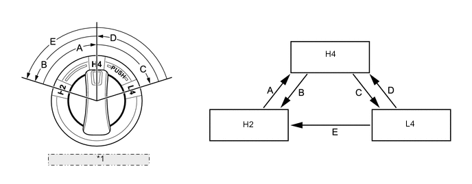
*1 Transfer Position Switch -
Switching to each mode is possible in the following conditions.
Models with Manual Transmission Switching Pattern Transfer Mode Switching Operation Condition A H2 → H4 Vehicle speed is 100 km/h (62 mph) or lower. B H4 → H2 - C H4 → L4
-
Vehicle is stopped or the vehicle speed is 3 km/h (2 mph) or lower.
-
Accelerator pedal is not depressed.
-
Clutch pedal is depressed.
D L4 → H4
-
Vehicle is stopped or the vehicle speed is 3 km/h (2 mph) or lower.
-
Accelerator pedal is not depressed.
-
Clutch pedal is depressed.
E L4 → H2
-
Vehicle is stopped or the vehicle speed is 3 km/h (2 mph) or lower.
-
Accelerator pedal is not depressed.
-
Clutch pedal is depressed.
Models with Automatic Transmission Switching Pattern Transfer Mode Switching Operation Condition A H2 → H4 Vehicle speed is 100 km/h (62 mph) or lower. B H4 → H2 - C H4 → L4
-
Vehicle is stopped.
-
Shift lever is in N.
D L4 → H4
-
Vehicle is stopped.
-
Shift lever is in N.
E L4 → H2
-
Vehicle is stopped.
-
Shift lever is in N.
-
-
-
DIAGNOSIS
-
When the 4 wheel drive control ECU detects a malfunction, the 4 wheel drive control ECU records the malfunction and memorizes the information related to the fault.
-
The 4 wheel drive control ECU will also store the Diagnostic Trouble Codes (DTCs) of the malfunctions. The DTCs stored in the 4 wheel drive control ECU are output to the Global TechStream (GTS) via the DLC3.
-
For details, refer to the Repair Manual.
-