LIGHTING SYSTEM
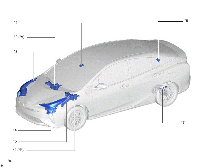
| *A | RHD Models | *B | LHD Models |
| *1 | FORWARD RECOGNITION CAMERA | *2 | BRAKE BOOSTER WITH MASTER CYLINDER ASSEMBLY
|
| *3 | HEADLIGHT ASSEMBLY RH
|
*4 | HEADLIGHT ASSEMBLY LH
|
| *5 | ENGINE ROOM RELAY BLOCK AND JUNCTION BLOCK ASSEMBLY
|
*6 | SMART DOOR CONTROL RECEIVER ASSEMBLY |
| *7 | REAR HEIGHT CONTROL SENSOR SUB-ASSEMBLY LH | - | - |
| *a | The illustrations shown are examples only. | - | - |
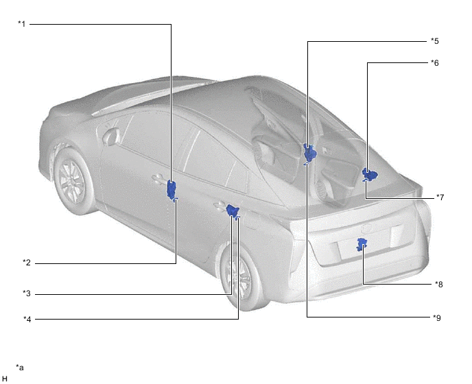
| *1 | FRONT DOOR LOCK WITH MOTOR ASSEMBLY LH | *2 | FRONT DOOR COURTESY LIGHT SWITCH ASSEMBLY (LH) |
| *3 | REAR DOOR LOCK ASSEMBLY LH | *4 | REAR DOOR COURTESY LIGHT SWITCH ASSEMBLY (LH) |
| *5 | FRONT DOOR LOCK WITH MOTOR ASSEMBLY RH | *6 | REAR DOOR LOCK ASSEMBLY RH |
| *7 | REAR DOOR COURTESY LIGHT SWITCH ASSEMBLY (RH) | *8 | BACK DOOR LOCK ASSEMBLY |
| *9 | FRONT DOOR COURTESY LIGHT SWITCH ASSEMBLY (RH) | - | - |
| *a | The illustrations shown are examples only. | - | - |
Figure 1. LHD Models
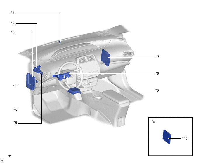
| *1 | AUTOMATIC LIGHT CONTROL SENSOR | *2 | No. 4 RELAY BLOCK
|
| *3 | MAIN BODY ECU(MULTIPLEX NETWORK BODY ECU) | *4 | INSTRUMENT PANEL JUNCTION BLOCK ASSEMBLY
|
| *5 | PARKING BRAKE SWITCH ASSEMBLY | *6 | STOP LIGHT SWITCH ASSEMBLY |
| *7 | HYBRID VEHICLE CONTROL ECU ASSEMBLY | *8 | HEADLIGHT DIMMER SWITCH ASSEMBLY |
| *9 | AIRBAG SENSOR ASSEMBLY | *10 | CERTIFICATION ECU (SMART KEY ECU ASSEMBLY) |
| *a | Refer to Service Bulletin for the installation position of the parts. | *b | The illustrations shown are examples only. |
Figure 2. RHD Models
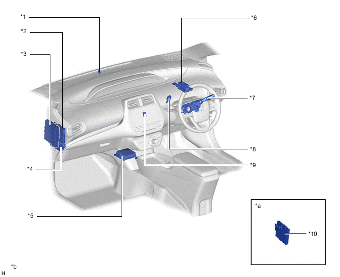
| *1 | AUTOMATIC LIGHT CONTROL SENSOR | *2 | MAIN BODY ECU(MULTIPLEX NETWORK BODY ECU) |
| *3 | HYBRID VEHICLE CONTROL ECU ASSEMBLY | *4 | INSTRUMENT PANEL JUNCTION BLOCK ASSEMBLY
|
| *5 | AIRBAG SENSOR ASSEMBLY | *6 | No. 4 RELAY BLOCK
|
| *7 | HEADLIGHT DIMMER SWITCH ASSEMBLY | *8 | STOP LIGHT SWITCH ASSEMBLY |
| *9 | PARKING BRAKE SWITCH ASSEMBLY | *10 | CERTIFICATION ECU (SMART KEY ECU ASSEMBLY) |
| *a | Refer to Service Bulletin for the installation position of the parts. | *b | The illustrations shown are examples only. |
Figure 3. LHD Models
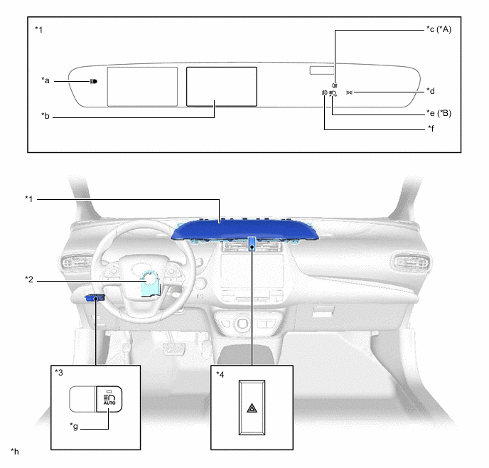
| *A | Models with Rear Fog Lights | *B | Models with Automatic High Beam System |
| *1 | COMBINATION METER ASSEMBLY | *2 | STEERING SENSOR |
| *3 | COMBINATION SWITCH ASSEMBLY | *4 | HAZARD WARNING SWITCH |
| *a | High Beam Indicator Light | *b | Multi-information Display |
| *c | Rear Fog Light Indicator Light | *d | Taillight Indicator Light |
| *e | Automatic High Beam Indicator Light | *f | Front Fog Light Indicator Light |
| *g | Automatic High Beam Switch | *h | The illustrations shown are examples only. |
Figure 4. RHD Models
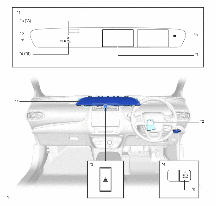
| *A | Models with Rear Fog Lights | *B | Models with Automatic High Beam System |
| *1 | COMBINATION METER ASSEMBLY | *2 | STEERING SENSOR |
| *3 | HAZARD WARNING SWITCH | *4 | COMBINATION SWITCH ASSEMBLY |
| *a | Rear Fog Light Indicator Light | *b | Front Fog Light Indicator Light |
| *c | Taillight Indicator Light | *d | Automatic High Beam Indicator Light |
| *e | High Beam Indicator Light | *f | Multi-information Display |
| *g | Automatic High Beam Switch | *h | The illustrations shown are examples only. |