AIR CONDITIONING SYSTEM
-
CONSTRUCTION
-
Ejector Cycle System (ECS) Type No. 1 Cooler Evaporator
-
The ECS type No. 1 cooler evaporator is composed of a tank, tubes and cooling fins. For the tubes, extrusion is used so that small passages are created, helping to achieve excellent heat transmission performance and to allow for a thinner design (38 mm). In addition, reductions in the height and pitch of the fins and reductions in the thickness of the tubes are achieved, helping to promote heat transmission and to allow for thinner core materials. The result of this is a significant reduction in size and weight of the evaporator. Also, clean coat is used for the main body of the evaporator, helping to suppress development of bacteria, which may cause bad smells, and chrome-free surface treatment is used in consideration of the environment.
-
The ejector is positioned in the ECS type No. 1 cooler evaporator top tank. The flow of the refrigerant is divided into the upwind and downwind sections as it passes through the evaporator, allowing for the ejector cycle (EJECS II)*.
Tech Tips
*: Ejector cycle (EJECS II) is a registered trademark owned by DENSO Corporation.
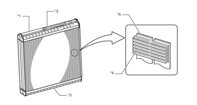
*1 Top tank *2 Ejector *3 Bottom tank *4 Cooling fin *5 Multiple passage tube - -
-
-
Ejector Cycle System Operation
-
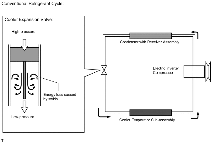
In a conventional refrigerant cycle, liquid refrigerant gas is sent into the cooler evaporator sub-assembly using the cooler expansion valve, generating cold air. However, a rapid decrease in the refrigerant pressure forms swirls, causing energy loss.
-
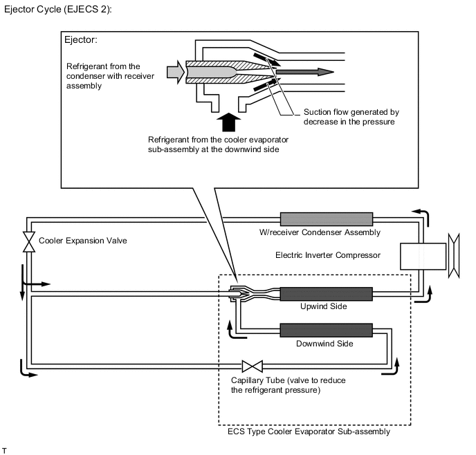
In this ejector cycle, the energy loss caused by the cooler expansion valve is utilized by the operation of the ejector that injects and expands a high-pressure refrigerant, thus reducing energy consumption.
-
-
Structure and operation of ejector
-
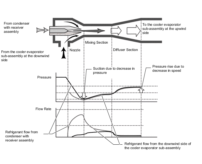
The ejector is composed of the nozzle, mixing and diffuser sections.
-
A high temperature and high pressure liquid refrigerant flowing from the condenser with receiver assembly is depressurized at the nozzle section and sucks in the low temperature and low pressure gaseous refrigerant from the No. 1 cooler evaporator on the downwind side. The refrigerants are mixed at the mixing section, and the flow speed is decreased at the diffuser section so that the refrigerant is pressurized and flows into the No. 1 cooler evaporator on the upwind side. This realizes the condition where the refrigerant pressure in the No. 1 cooler evaporator on the downwind side is considerably lower than that on the upwind side, creating the lower temperature conditions. Therefore, air cooled by the No. 1 cooler evaporator on the upwind side can be further cooled by the No. 1 cooler evaporator on the downwind side, thus improving the efficiency of the No. 1 cooler evaporator.
-
As a result of this, energy efficiency and cooling performance are enhanced. This allows for the reduction in the rotation speed of the electric inverter compressor, resulting in lower power consumption of the air conditioning.
-
-