INTELLIGENT CLEARANCE SONAR SYSTEM
-
FUNCTION OF MAIN COMPONENTS
Component Function Front Corner Ultrasonic Sensor (FL/FR) Detects the distance between the vehicle and an obstacle. Front Center Ultrasonic Sensor (FLC/FRC) Rear Corner Ultrasonic Sensor (RL/RR) Rear Center Ultrasonic Sensor (RLC/RRC) Clearance Warning ECU Assembly
-
Detects obstacles using information from each ultrasonic sensor, determines settings based on information from various sensors, switches and ECUs, and controls the intelligent clearance sonar system.
-
Sends the driving torque restriction control request signal to the hybrid vehicle control ECU.
-
Sends the brake control request signal to the skid control ECU.
-
Sends the intelligent clearance sonar system information to the combination meter assembly and headup display*.
-
Sounds the No. 1and No. 2 clearance warning buzzer.
Combination Meter Assembly
-
Multi-information Display
-
ICS OFF Indicator Light
-
Sends the intelligent clearance sonar system on/off signal to the clearance warning ECU assembly.
-
The ICS OFF indicator light illuminates when the intelligent clearance sonar system is off.
-
Based on information from the clearance warning ECU assembly, displays information related to the intelligent clearance sonar system on the multi-information display and sounds the buzzer in accordance with the situation.
Headup Display* Displays the intelligent clearance sonar system information. No. 1 Clearance Warning Buzzer (Front) Sounds to inform the driver according to the distance to the obstacle. No. 2 Clearance Warning Buzzer (Rear) Steering Pad Switch Assembly Sends operation signals from switches to the spiral cable with sensor sub-assembly. Spiral Cable with Sensor Sub-assembly Sends operation signals from the steering pad switch assembly to the combination meter assembly. Accelerator Pedal Sensor Assembly Detects the amount of pedal effort applied to the accelerator pedal and outputs the signal to the hybrid vehicle control ECU. Shift Lock Control Unit Assembly
-
Shift Lever Position Sensor
Sends the shift position signal to the hybrid vehicle control ECU. Hybrid Vehicle Control ECU Sends the shift position signal to the clearance warning ECU. Stop Light Switch Assembly Detects if the brake pedal is depressed and outputs a signal to the skid control ECU. Speed Sensors Detect the wheel speed of each of the 4 wheels and outputs the signal to the skid control ECU. Brake Booster with Master Cylinder Assembly
-
Skid Control ECU
-
Servo Pressure Sensor
Sends the vehicle speed signal, stop light switch on signal and servo pressure signal to the clearance warning ECU assembly. Steering Sensor Sends the steering angle signal to the clearance warning ECU assembly. Airbag ECU Assembly Detects the yawrate and lateral/longitudinal deceleration of the vehicle and sends the signal to the clearance warning ECU assembly. Air Conditioning Amplifier Assembly Sends outside temperature information to the clearance warning ECU assembly. Main Body ECU (Multiplex Network Body ECU) Sends model destination signal (information to indicate the market the vehicle was built for) to the clearance warning ECU assembly. *: Models with headup display
-
-
SYSTEM CONTROL
-
Driving Torque Restriction Control
-
When all of the following conditions are met, driving torque restriction control is performed.
-
The power switch is on (IG).
-
The intelligent clearance sonar system is on.
-
An obstacle is detected by an ultrasonic sensor.
-
Vehicle speed is 15 km/h or less.
-
A collision is unavoidable unless the brakes are strongly applied.
-
-
When any of the following conditions are met, the driving torque restriction control will not operate.
-
The power switch is off.
-
The intelligent clearance sonar system is off.
-
No obstacle is detected by the ultrasonic sensors.
-
A collision is avoidable with normal operation of the brake.
-
-
-
Brake Control
-
When all of the following conditions are met, brake control is performed.
-
Driving torque restriction control is being performed.
-
A collision is unavoidable unless emergency braking is performed.
-
-
When any of the following conditions are met, driving torque restriction control will not operate.
-
The intelligent clearance sonar system is off.
-
The brake pedal is depressed after the vehicle is stopped by brake control operation.
-
Approximately 2 seconds are elapsed after the vehicle is stopped due to the brake control.
-
No obstacle is detected by the ultrasonic sensors.
Tech Tips
When brake control is performed, the intelligent clearance sonar system turns off automatically. The intelligent clearance sonar system turns on again when no obstructions are detected by the ultrasonic sensors, the shift lever is moved to reverse (R) with drive (D) selected or is moved to drive (D) with reverse (R) selected, the power switch is turned off and then turned on (IG), or by using settings screen on the multi-information display.
-
-
-
Detection range of the ultrasonic sensor
-
The detection range of the ultrasonic sensors is approximately 4000 mm (157.5 in.). The detection range may vary depending on the shape of the object.
-
When the vehicle is moving forward, the intelligent clearance sonar system operates when the front corner ultrasonic sensor LH, front corner ultrasonic sensor RH, front center ultrasonic sensor LH and front center ultrasonic sensor RH detect an obstacle at the same time. When the vehicle is moving rearward, the intelligent clearance sonar system operates when the rear corner ultrasonic sensor LH, rear corner ultrasonic sensor RH, rear center ultrasonic sensor LH and rear center ultrasonic sensor RH detect an obstacle at the same time.
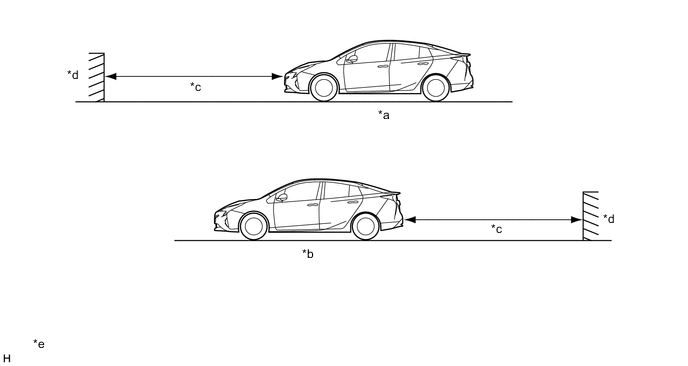
*a When the vehicle is moving forward. *b When the vehicle is moving rearward. *c Approximately 4000 mm (157.5 in.) *d Object *e The detection range shown in the illustration is for when detecting an object that is 2000 mm (78.7 in.) wide, 1000 mm (39.4 in.) tall and is perpendicular to the ground. - - Tech Tips
Depending on the vehicle condition, the intelligent clearance sonar system may not operate even when the ultrasonic sensors detect an object.
-
-
intelligent clearance sonar system
-
The intelligent clearance sonar system controls the vehicle based on signals received by the clearance warning ECU from various sensors, switches and ECUs.
-
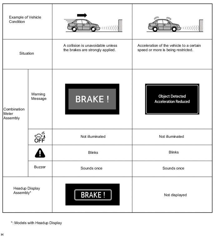
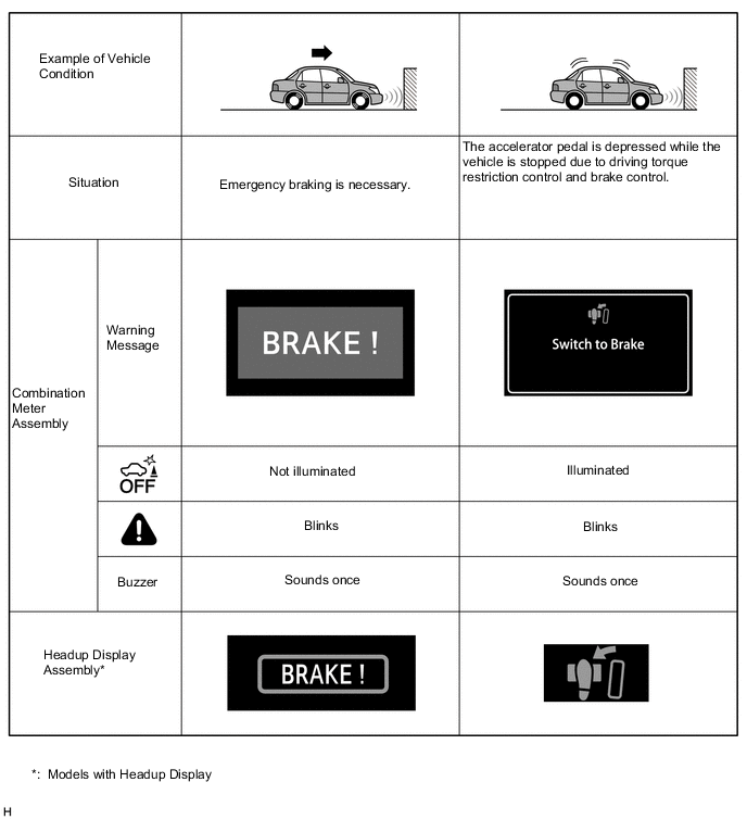
When each control of the intelligent clearance sonar system is being performed, the indicator light illuminates, a warning message is displayed on the multi-information display and buzzer sounds to alert the driver.
-
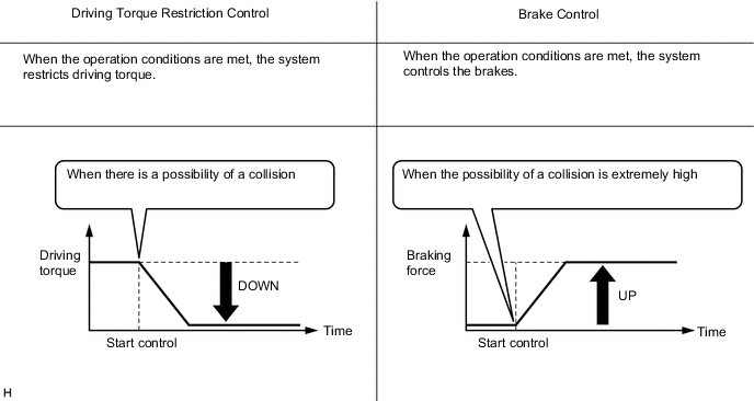
Driving torque restriction control is performed when the ultrasonic sensors detect an object and it is determined that there is a possibility of a collision while the vehicle is being driven at a speed of approximately 15 km/h (9 mph) or less.
Figure 1. Driving Torque Restriction Control
-
When it is determined that the possibility of a collision is extremely high even when driving torque restriction control has been performed, brake control is performed.
Figure 2. Driving Torque Restriction Control and Brake Control
-
-
Unnecessary operation of the intelligent clearance sonar system
-
In the following situations, an ultrasonic sensor may not operate correctly or the intelligent clearance sonar system may operate even when there is a low possibility of a collision.
-
Environmental influence
-
There is an obstacle on the shoulder of the road (when the vehicle is driven in a narrow tunnel, on a narrow bridge or on a narrow road).
-
When the vehicle is being driven on grass or a bumpy or gravel road.
-
The vehicle is driven toward a banner or flag, a low-hanging branch or a boom barrier (such as those used at railroad crossings, toll gates and parking lots).
-
When the vehicle is being driven toward a tall curbstone or the corner of a curbstone.
-
The vehicle is being parallel parked.
-
The vehicle is being driven on a steep slope.
-
Objects located lower than the ultrasonic sensors or thin objects.
-
The vehicle is being driven on a narrow road.
-
There is a rut or hole in the surface of the road.
-
When the vehicle is driven on a metal cover (grating), such as those used for drainage ditches.
-
Water is covering an ultrasonic sensor due to a flooded road.
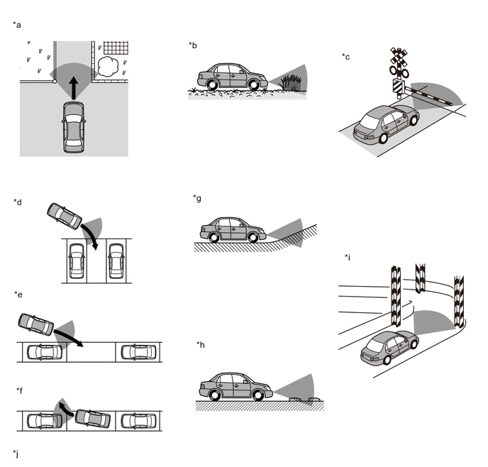
*a There is an obstacle on the shoulder of the road (when the vehicle is driven in a narrow tunnel, on a narrow bridge or on a narrow road). *b When the vehicle is being driven on gravel road, or on grass. *c The vehicle is driven toward a banner or flag, a low-hanging branch or a boom barrier (such as those used at railroad crossings, toll gates and parking lots). *d When the vehicle is being reversed into a perpendicular parking space without using perpendicular parking assist mode of the simple intelligent parking assist system. *e When the vehicle is being driven to a parallel parking space without using parallel parking assist mode of the simple intelligent parking assist system. *f When the vehicle is being driven out of a parallel parking space without using parallel parking departure assist mode of the simple intelligent parking assist system. *g The vehicle is being driven on a steep slope. *h Objects located lower than the ultrasonic sensors or thin objects. *i The vehicle is being driven on a narrow road. *j The illustration shown is an example only. Tech Tips
Even if the intelligent clearance sonar system operates while on a railroad crossing, brake control will be automatically be canceled after approximately 2 seconds. Brake control can also be canceled by depressing the brake pedal. After brake control is canceled, depress the accelerator pedal to drive out of the railroad crossing.
-
-
Influence from the weather
-
When the vehicle is operated under the hot sun or in a freezing climate.
-
When an ultrasonic sensor is frozen.
-
When foreign matter such as ice, snow or mud is attached to the ultrasonic sensors.
-
When there is a downpour, or water is splashing on the vehicle.
-
In severe weather such as fog, snow or a sandstorm.
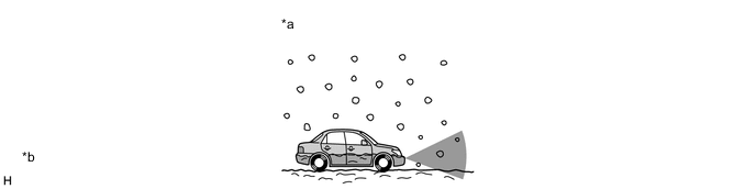
*a When foreign matter such as ice, snow or mud is attached to the ultrasonic sensors. *b The illustration shown is an example only. -
-
Influence from other ultrasonic waves
-
When ultrasonic waves are received from the horn or parking sonar system of another vehicle, a motorcycle engine, or the air brakes of a large vehicle.
-
When an antenna for a wireless transmitter is mounted on the vehicle.
-
-
Influence from installed accessories
-
Electronic components such as a backlit license plate (especially fluorescent types), fog lights, a fender pole or a wireless antenna are installed near the sensors.
-
When a towing hitch is mounted on the vehicle.
-
-
Changes in the vehicle.
-
The height of the vehicle has drastically changed due to loading (the nose tilts up or down).
-
When the vehicle posture tilts significantly.
-
When the bumper is damaged.
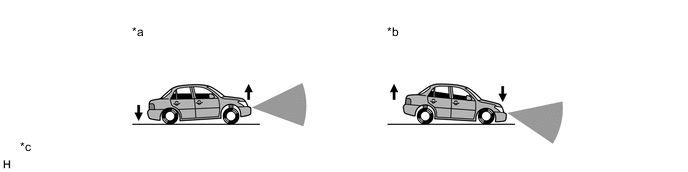
*a The height of the vehicle has drastically changed due to loading (the nose tilts up). *b The height of the vehicle has drastically changed due to loading (the nose tilts down). *c The illustration shown is an example only. - - -
-
Others
-
The vehicle is being loaded onto a ship, truck or other transport vessel.
-
The vehicle is driven continuously when using a drum tester such as a speedometer tester, brake/speedometer combination tester or chassis dynamometer.
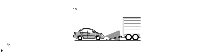
*a The vehicle is being loaded onto a ship, truck or other transport vessel. *b The illustration shown is an example only. -
-
-
-
FUNCTION
-
Intelligent clearance sonar system on/off setting
-
The intelligent clearance sonar system can be turned on or off via the setting screen displayed on the multi-information display.
-
The ICS OFF indicator light is located in the combination meter assembly so that the driver can see whether the intelligent clearance sonar system is on. When the intelligent clearance sonar system is off, the ICS OFF indicator light illuminates.
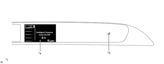
*a Multi-information Display *b ICS OFF Indicator Light *c The illustration shown is an example only. The illustration may differ from the actual vehicle screen. - -
-
-
-
FAIL-SAFE
-
When the clearance warning ECU assembly detects a malfunction in the system, the system enters fail-safe mode. For details, refer to the Repair Manual.
-
-
DIAGNOSIS
-
If a system malfunction is detected, the clearance warning ECU assembly stores Diagnostic Trouble Codes (DTCs) in its memory. For details, refer to the Repair Manual.
-