PARKING BRAKE SYSTEM
-
CONSTRUCTION
-
Parking brake consists of a crank lever, actuator and sleeve nut. The crank lever transmits the depression force of the parking brake pedal to the input shaft of the actuator. The actuator converts the rotational force of the input shaft to a linear force that pushes the adjusting bolt. The sleeve nut transmits the force of the adjusting bolt to the piston.
-
The adjuster consists of an adjusting bolt and sleeve nut. The adjusting bolt adjusts to provide the increased length that is required as the piston protrudes due to pad wear. Also, a bearing is provided so that the sleeve nut rotates smoothly.
Figure 1. Parking Brake Components
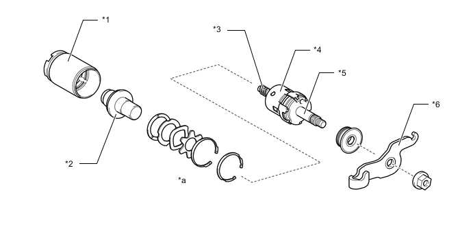
*1 Piston *2 Sleeve Nut *3 Adjusting Bolt *4 Actuator *5 Input Shaft *6 Crank Lever *a Bearing - -
-
-
OPERATION
-
Operation of the parking brake mechanism
-
The crank lever rotates via the parking brake cable when the parking brake pedal is depressed.
-
The crank lever rotates the input shaft which moves the check balls to a shallower part of their groove within the input shaft. The adjusting bolt is pushed out proportional to the change in the depth of the groove.
-
The adjusting bolt pushes the brake pad against the disc rotor via the sleeve nut and piston and subsequently generates braking force.
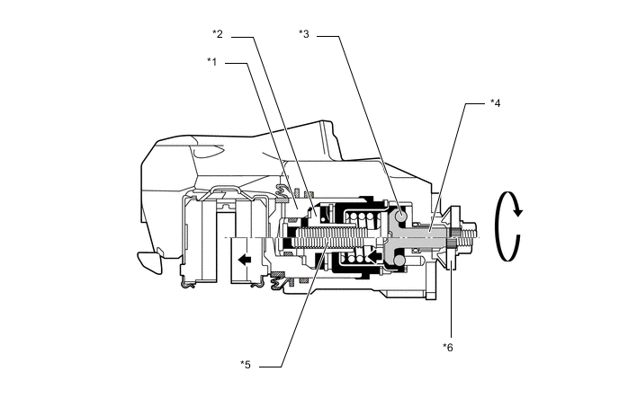
*1 Piston *2 Sleeve Nut *3 Check Ball *4 Input Shaft *5 Adjusting Bolt *6 Crank Lever
-
-
Adjuster Operation
-
When the brake pad has worn and the clearance between the brake pad and disc rotor is certain value or more, the sleeve nut is rotated along the thread of the adjusting bolt by brake fluid pressure. With this, the clearance caused by brake pad wear is automatically adjusted. Also, the sleeve nut has a clutch that engages during the adjustment to prevent excessive rotation.
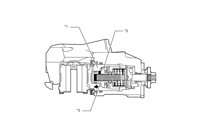
*1 Piston *2 Sleeve Nut *3 Adjusting Bolt - -
-
-