BRAKE SYSTEM
-
CONSTRUCTION
-
The master cylinder consists of an input piston, output piston, master cylinder piston, regulator and an operating rod which is directly connected to the brake pedal.
-
The operating rod and input piston directly transmit the depression force of the brake pedal.
-
Fluid pressure which is controlled by the regulator is introduced to the servo chamber to push the output piston and master cylinder piston. Also, a return spring is used for the input piston, output piston and master cylinder piston to create a return force when there is no brake fluid pressure.
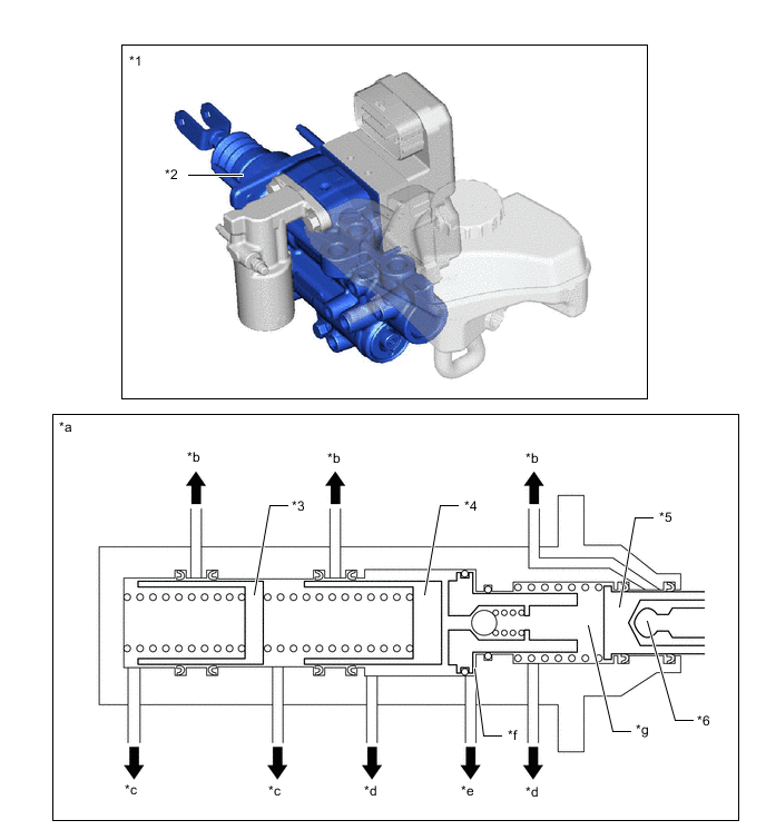
*1 Brake Booster with Master Cylinder Assembly *2 Master Cylinder *3 Master Cylinder Piston *4 Output Piston *5 Input Piston *6 Operating Rod *a Master Cylinder Cross Section *b To Brake Master Cylinder Reservoir Assembly *c To Wheel Cylinder *d To Stroke Simulator *e To Regulator *f Servo Chamber *g Gap Hold Chamber - -
-
-
OPERATION
-
When the brake pedal is depressed, the brake pedal moves the input piston which is directly connected to the operating rod. Brake fluid pressure which is generated by the depression force of the brake pedal is applied to the stroke simulator. The linear solenoid valve (SLA) is opened in accordance with the brake fluid pressure to control the brake fluid pressure which is generated by the brake booster pump assembly, which is then applied to the servo chamber via the regulator. The brake fluid pressure applied to the servo chamber pushes the output piston and master cylinder piston which generates brake fluid pressure in the wheel cylinder.
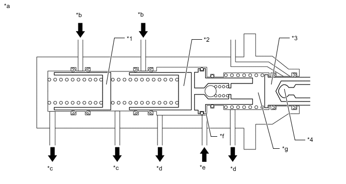
*1 Master Cylinder Piston *2 Output Piston *3 Input Piston *4 Operating Rod *a Master Cylinder Cross Section *b To Brake Master Cylinder Reservoir Assembly *c To Wheel Cylinder *d To Stroke Simulator *e To Regulator *f Servo Chamber *g Gap Hold Chamber - - -
When the brake pedal is depressed and held by the driver and the depression force of the brake pedal and the brake fluid pressure in the wheel cylinders are balanced, the linear solenoid valve (SLA) is closed to maintain the pressure in the servo chamber.
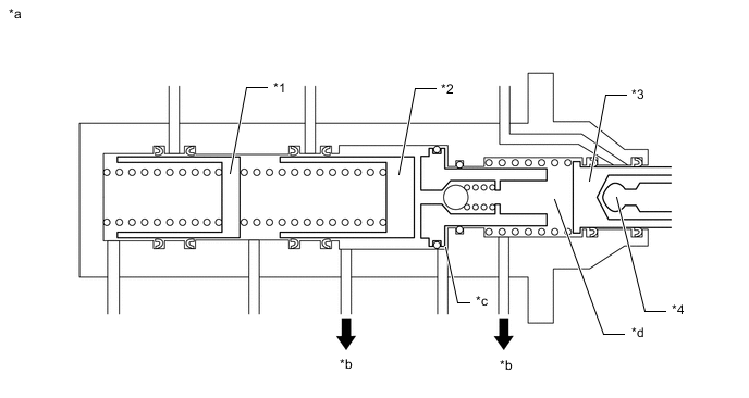
*1 Master Cylinder Piston *2 Output Piston *3 Input Piston *4 Operating Rod *a Master Cylinder Cross Section *b To Stroke Simulator *c Servo Chamber *d Gap Hold Chamber -
When the brake pedal is released, fluid pressure generated by the depression force of the brake pedal is not applied to the stroke simulator. The linear solenoid valve (SLR) is opened and the output piston and master cylinder return to their original position and the brake fluid pressure in the wheel cylinders reduces.
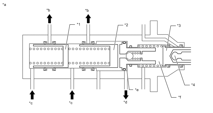
*1 Master Cylinder Piston *2 Output Piston *3 Input Piston *4 Operating Rod *a Master Cylinder Cross Section *b To Brake Master Cylinder Reservoir Assembly *c To Wheel Cylinder *d To Regulator *e Servo Chamber *f Gap Hold Chamber
-