HYBRID TRANSAXLE SYSTEM
-
CONSTRUCTION
-
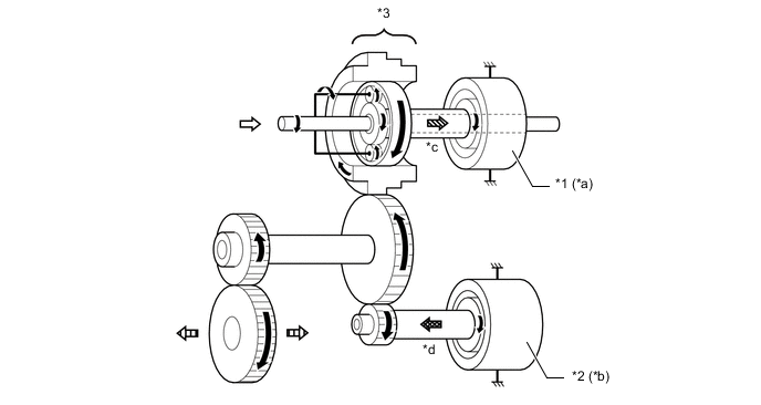
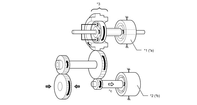
The compound gear unit consists of the power split planetary gear unit. Each planetary ring gear is integrated with the compound gear. Furthermore, this compound gear is integrated with a counter drive gear and parking lock gear.
-
The power split planetary gear unit splits the motive force of the engine into 2 passages. One passage provides motive force to drive the wheels, and the other provides force to drive generator (MG1), so that the generator (MG1) can function as a generator.
-
Power from the motor (MG2) is transferred to the counter driven gear via the MG2 reduction gear in order to drive the final drive gears.
Tech Tips
The ratio of the motor (MG2) revolution speed and counter drive gear revolution speed is 3.823.
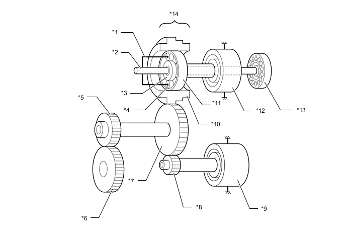
*1 Carrier *2 Input shaft *3 Sun Gear *4 Pinion Gear *5 Final Drive Gear *6 Final Driven Gear *7 Counter Driven Gear *8 MG2 Reduction Gear *9 Motor (MG2) *10 Counter Drive Gear (Compound Gear) *11 Ring Gear *12 Generator (MG1) *13 Oil Pump *14 Power Split Planetary Gear Unit -
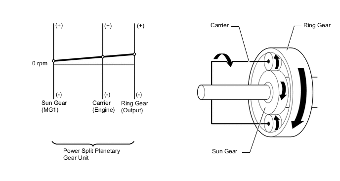
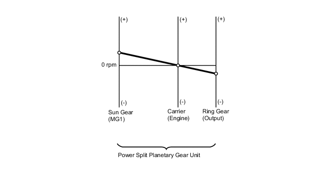
How to Read Nomographic Charts
-
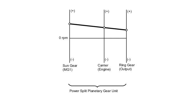
The nomographic chart below gives a visual representation of the planetary gear rotation direction, rotational speed and torque balance.
-
In the nomographic chart, a straight line is used to represent the relationship between the rotation directions and rotational speeds of the 3 gears in the planetary gear. The rotational speed of each gear is indicated by the distance from the 0 rpm point. Due to the structure of the planetary gear, the relationship between the rotational speeds of the 3 gears is always expressed by a straight line.
-
The nomographic charts and illustrations of the gear train operation for each vehicle driving condition shown in the following descriptions are examples only. The examples shown are 'snapshots', whereas normal system operation is a constantly changing blend of conditions and system reactions to suit those conditions.
Figure 1. Nomographic Chart
-
-
Torque and Rotation Relationship
-
In the hybrid system, the motor generators have different roles depending on the situation. Understanding the relationship between the rotation direction and torque can help to make the role of a motor generator easier to understand.
-
The table below shows the relationship of drive and electric generation for different combinations of positive or negative torque and forward or reverse rotation.
Rotation Direction Torque Condition Role of Component Forward (+) Rotation Positive Torque Drive Negative Torque Electric Generation Reverse (-) Rotation Positive Torque Electric Generation Negative Torque Drive -
As an example, if a motor generator is rotating in the forward (+) direction and it applies negative torque, it will generate electricity (producing electrical power).
-
Alternately, if the motor generator is rotating in the reverse (-) direction and it applies negative torque, it will act as a drive source (consuming electrical power).
-
-
The connection of the sun gear, ring gear and carrier of each planetary gear unit is as shown below.
Item Connection Power Split Planetary Gear Unit Sun Gear Generator (MG1) Carrier Input Shaft (Engine) Ring Gear Counter Drive Gear (Compound Gear) MG2 Reduction Gear Drive Gear Motor (MG2) Driven Gear Counter Driven Gear (Output)
-
-
OPERATION
-
READY ON State
-
Current is sent to the generator (MG1) which functions as a starter for the engine and starts the engine via the sun gear.
Tech Tips
When the engine is started, positive torque is applied to the motor (MG2) to cancel the engine reaction force.
Figure 2. READY-ON State when Starting Engine (Vehicle Stopped)
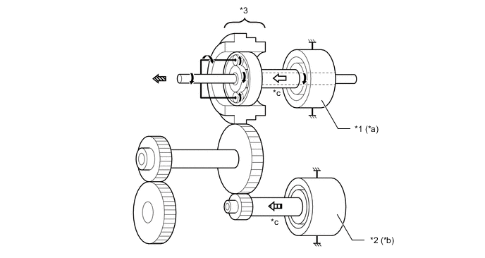
*1 Generator (MG1) *2 Motor (MG2) *3 Power Split Planetary Gear Unit - - *a Drive *b Stopped *c Positive Torque - - 
Rotation Direction 
From Generator (MG1) 
To Engine 
From Motor (MG2) Figure 3. Nomographic Chart (Vehicle Stopped)
-
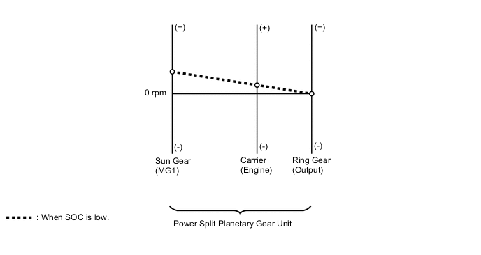
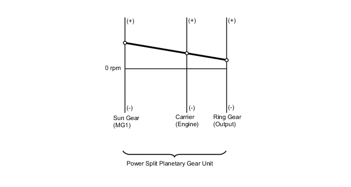
If the SOC of the HV battery is low, it is charged by the generator (MG1), which is driven by the engine.
-
The engine motive force, which is input by the carrier, is output to the sun gear. Thus, motive force is transmitted in order to operate the generator (MG1) as a generator.
Tech Tips
When the vehicle is stopped, negative torque is applied to the motor (MG2) to prevent the tires from rotating.
Figure 4. Charging when Stopped
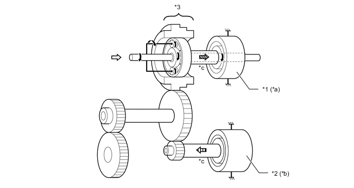
*1 Generator (MG1) *2 Generator (MG1) *3 Power Split Planetary Gear Unit - - *a Driven - Generates Electricity *b Stopped *c Negative Torque - - Rotation Direction From Engine To Generator (MG1) From Motor (MG2) Figure 5. Nomographic Chart
-
-
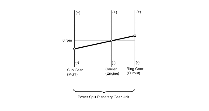
Starting Off and Low Load Cruising
-
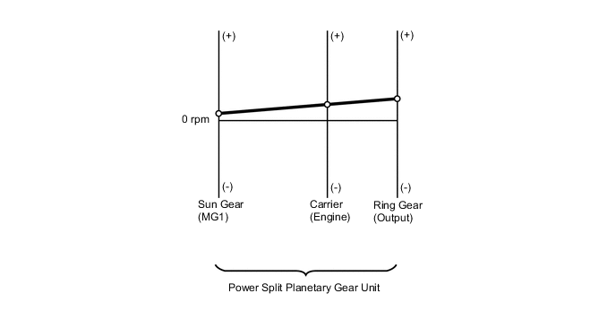
When the HV battery state of charge (SOC) is sufficient, the vehicle starts off and runs using only the motive force of the motor (MG2). In this case, the engine is stopped and the motor generator (MG1) does not generate electricity.
Figure 6. Starting Off and Low Load Cruising

*1 Generator (MG1) *2 Motor (MG2) *3 Power Split Planetary Gear Unit - - *a Rotates Freely *b Drive *c Positive Torque - - Rotation Direction From Motor (MG2) To Front Wheels - - Figure 7. Nomographic Chart
-
If the SOC of the HV battery is low, it is charged by the generator (MG1), which is driven by the engine. This power is also used to power the motor (MG2).
-
The engine motive force, which is input by the carrier, is output to the ring gear. The motive force of the motor (MG2) is output to the ring gear via the MG2 reduction gear. The combination of these 2 motive forces is transmitted by the compound gear in order to drive the front wheels.
Figure 8. Starting Off and Low Load Cruising when SOC Low
*1 Generator (MG1) *2 Motor (MG2) *3 Power Split Planetary Gear Unit - - *a Driven - Generates Electricity *b Drive *c Negative Torque *d The torque condition can be positive or negative depending on the driving condition. Rotation Direction From Engine To Generator (MG1) To Front Wheels 
From Motor (MG2) or To Motor (MG2) - - Figure 9. Nomographic Chart
-
-
Constant-speed Cruising
-
When the vehicle is running under low load and constant-speed cruising conditions, the engine will be operated in its most efficient range to power the vehicle.
-
The engine motive force, which is input by the carrier, is output to the ring gear. The motive force of the motor (MG2) is output to the ring gear via the MG2 reduction gear. The combination of these 2 motive forces is transmitted by the compound gear in order to drive the front wheels.
Figure 10. Constant-speed Cruising
*1 Generator (MG1) *2 Motor (MG2) *3 Power Split Planetary Gear Unit - - *a Driven - Amount of Electricity Generated is Low *b Drive *c Negative Torque *d The torque condition can be positive or negative depending on the driving condition. Rotation Direction From Engine To Generator (MG1) To Front Wheels From Motor (MG2) or To Motor (MG2) - - Figure 11. Nomographic Chart
-
If the SOC of the HV battery is low, more engine power is provided to increase the generation of electricity via the generator (MG1). This charges the HV battery.
Figure 12. Constant-speed Cruising when SOC Low
*1 Generator (MG1) *2 Motor (MG2) *3 Power Split Planetary Gear Unit - - *a Driven - When SOC is Low, Greater Amount of Electricity is Generated. *b Drive *c Negative Torque *d The torque condition can be positive or negative depending on the driving condition. Rotation Direction From Engine To Generator (MG1) To Front Wheels From Motor (MG2) or To Motor (MG2) - - Figure 13. Nomographic Chart
-
-
During Full Throttle Acceleration
-
When the vehicle driving condition changes from low load cruising to full-throttle acceleration, this system supplements the motive force of the motor (MG2) with electrical power from the HV battery.
-
The engine motive force, which is input by the carrier, is output to the ring gear. The motive force of the motor (MG2) is output to the ring gear via the MG2 reduction gear. The combination of these 2 motive forces is transmitted by the compound gear in order to drive the front wheels.
Figure 14. During Full Throttle Acceleration
*1 Generator (MG1) *2 Motor (MG2) *3 Power Split Planetary Gear Unit - - *a Driven - Generates Electricity *b Drive *c Negative Torque *d Positive Torque Rotation Direction From Engine To Generator (MG1) To Front Wheels From Motor (MG2) - - Figure 15. Nomographic Chart
-
-
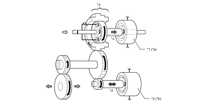
During Deceleration
-
While the vehicle is being driven with the shift lever in D and it decelerates, the engine turns off and the engine motive force output to the front wheels will be zero. At this time, the wheels drive the motor (MG2), causing the motor (MG2) to operate as a generator and charge the HV battery. While the motor (MG2) is operating as a generator, it creates resistance to the rotation of the front wheels, producing a braking effect.
-
The motive force of front wheels is transmitted via the counter gear and is output to the sun gear in order to drive the motor (MG2).
Figure 16. During Deceleration
*1 Generator (MG1) *2 Motor (MG2) *3 Power Split Planetary Gear Unit - - *a Rotates Freely *b Driven - Generates Electricity *c Negative Torque - - Rotation Direction To Motor (MG2) From Front Wheels - - Figure 17. Nomographic Chart
-
-
During in Reverse
-
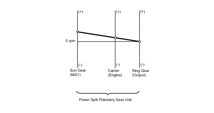
The vehicle is driven mainly by the motive force of the motor (MG2). When the HV battery state of charge (SOC) is low, the engine is operated and electricity generated by the generator (MG1) is used.
Figure 18. Driving in Reverse
*1 Generator (MG1) *2 Motor (MG2) *3 Power Split Planetary Gear Unit - - *a Rotates Freely *b Drive *c Negative Torque - - Rotation Direction From Motor (MG2) To Front Wheels - - Figure 19. Nomographic Chart
-
-