HYBRID TRANSAXLE SYSTEM
-
OUTLINE
-
A P610 hybrid vehicle transaxle is used.
-
Containing the motor (MG2) for driving the vehicle and generator (MG1) for generating electrical power, this transaxle uses a continuously variable transmission mechanism with a compound gear unit that achieves smooth and quiet operation.
-
This hybrid vehicle transaxle assembly consists primarily of a generator (MG1), motor (MG2), power split planetary gear unit, counter gear, final gear, differential gear unit and oil pump.
-
By utilizing a pluriaxial configuration for the generator (MG1) and the motor (MG2), the overall length of the transaxle has been shortened. A compound gear that consists of the ring gear of the power split planetary gear, counter drive gear and parking lock gear is utilized to drastically reduce size and weight. By using high accuracy machining for the gear tooth surfaces, low-loss bearings and an oil sling type lubrication mechanism, driving losses have been reduced resulting in improved fuel economy and reduced noise.
-
This transaxle has a 4-shaft configuration. The power split planetary gear unit, an oil pump and generator (MG1) are provided on the main shaft. The MG2 reduction gear and motor (MG2) are provided on the 2nd shaft. The counter driven gear and the final drive gear are provided on the 3rd shaft. The final driven gear and the differential gear unit are provided on the 4th shaft.
-
A differential pre-torque mechanism is used. Straightline stability and acceleration performance during periods of low load and low differential rotation when the vehicle is being driven normally are ensured.
-
Lubrication for each gear is performed via the trochoid oil pump of the main shaft and final driven gear slinging up ATF. Through the use of a lubrication structure (oil sling type lubrication method) in which the gears sling up ATF, reduction of oil pump drive loss and enhanced transmission efficiency of the powertrain system have been achieved. Also, a water-cooled type oil cooler which optimizes the flow of ATF is used to achieve high cooling performance, resulting in a high efficiency and high output powertrain.
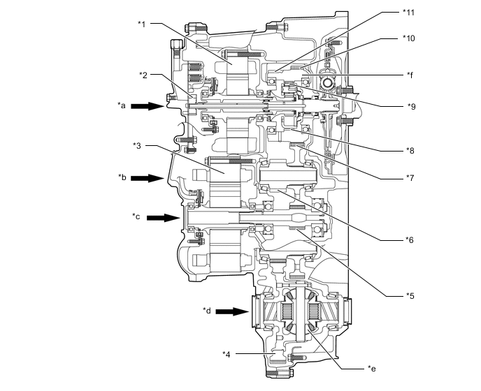
*1 Generator (MG1) *2 Oil Pump *3 Motor (MG2) *4 Final Driven Gear *5 MG2 Reduction Gear *6 Final Drive Gear *7 Counter Driven Gear *8 Planetary Ring Gear *9 Power Split Planetary Gear Unit *10 Counter Drive Gear *11 Parking Lock Gear - - *a Main Shaft *b 3rd Shaft *c 2nd Shaft *d 4th Shaft *e Differential Gear Unit *f Compound Gear
-
-
SPECIFICATION
Item Specification Transaxle Type P610 Shift Position P / R / N / D / B Power Split Planetary Gear Unit No. of Sun Gear Teeth 30 No. of Pinion Gear Teeth 23 No. of Ring Gear Teeth 78 MG2 Reduction Gear No. of Drive Gear Teeth 17 No. of Driven Gear Teeth 53 Counter Gear No. of Drive Gear Teeth 65 No. of Driven Gear Teeth 53 Final Gear No. of Drive Gear Teeth 21 No. of Driven Gear Teeth 73 Total Speed Reduction Ratio*1 2.834 Fluid Type Toyota Genuine ATF WS Fluid Capacity Liters (US qts, Imp. qts) 3.6 (3.8, 3.2) Weight (Reference)*2 kg (lb) 81.3 (179.2) *1: The ratio of the combination of the counter and final gears.
*2: Weight shows the figure with the fluid fully filled.