LANE DEPARTURE ALERT SYSTEM(w/ Steering Control)
-
FUNCTION OF MAIN COMPONENTS
Components Function Combination Meter Assembly Transmits a turn signal command to the forward recognition camera. Combination Meter Assembly
-
LDA Indicator Light
-
Steering Indicator Light
Illuminates or turns off in accordance with signals from the forward recognition camera. Multi-information Display Displays a warning message and white lines to inform or warn the driver of the system condition in accordance with signals from the forward recognition camera. Master Warning Light Illuminates to warn the driver in accordance with signals from the forward recognition camera. Multi Buzzer Sounds to warn the driver in accordance with signals from the forward recognition camera. Forward Recognition Camera
-
Captures a view of the road ahead of the vehicle and detects lane markers on the driving lane, and calculates the radius to the center of the lane, lane width, distance from markers and heading angle deviation.
-
Controls the LDA system.
-
Transmits the indicator illumination request signal, multi-information display indication request signal, and buzzer sound request signal to the combination meter assembly.
-
Receives vehicle information and turn signal light operation signals and sends a steering force signal to the power steering ECU assembly.
Millimeter Wave Radar Sensor Assembly Radiates millimeter waves forward, uses the reflected waves to detect the presence of a vehicle traveling ahead, the vehicle-to-vehicle distance, and the relative speed, and then transmits this information to the forward recognition camera. Driving Support ECU Assembly Transmits the LDA main switch signal to the forward recognition camera. Hybrid Vehicle Control ECU Sends the accelerator pedal opening angle signal to the forward recognition camera. Headlight Dimmer Switch Assembly Transmits a turn signal command to the combination meter assembly. Brake Booster with Master Cylinder Assembly Skid Control ECU Sends a vehicle speed signal from the speed sensor to the forward recognition camera. Steering Pad Switch Assembly LDA Main Switch Detects an on/off status of the system and transmits a signal to the forward recognition camera. Meter Control Switch Changes the customize settings of the lane departure warning function, LDA steering control function and vehicle sway warning function. Airbag ECU Assembly Yawrate Sensor Detects yaw rate and transmits a signal to the forward recognition camera. Steering Sensor Sends the turning angle of the steering wheel to the forward recognition camera. Power Steering ECU Assembly
-
Controls the power steering motor and performs steering assist based on signals received from the forward recognition camera.
-
Sends steering torque signals from the torque sensor to the power steering ECU assembly.
-
Detects steering operations performed by the driver and outputs the operations to the forward recognition camera.
-
Cancels steering assist when an abnormal torque request signal is received from the forward recognition camera.
Main Body ECU (Multiplex Network Body ECU) Sends country specification information signals to the forward recognition camera. Network Gateway ECU Gateway function of CAN communication. -
-
OPERATION CONDITION
-
Operating Conditions of LDA System (Steering Assist Unavailable)
Operation Condition Operating/Resume The LDA system (steering assist unavailable) is activated when all of the following conditions are met:
-
The LDA main switch is on. (When the LDA main switch is pressed to turn on the LDA system, the LDA indicator light illuminates.)
-
The vehicle speed is above approximately 50 km/h (32 mph).
-
Lane markers are detected.
-
LDA system becomes activated when the turning signal is set to the opposite direction against the heading direction.
-
System malfunction is not detected.
Suspended The LDA system (steering assist unavailable) is suspended when any one of the following conditions is met:
-
The vehicle speed is less than approximately 50 km/h (32 mph).
-
A turn signal command is detected.
-
No lane markers are detected.
-
Immediately after the LDA is activated.
-
A malfunction is detected in the LDA system.
-
The temperature of the forward recognition camera is abnormal.
-
The vehicle crosses halfway or further over a lane marker.
Canceled The LDA system (steering assist unavailable) is stopped when any one of the following conditions is met:
-
The LDA main switch is off.
-
The LDA system is malfunctioning.
-
Power switch is turned off.
The LDA system (steering assist unavailable) resumes when the following conditions are met:
-
The conditions to start operation listed above returns to are satisfied.
-
The LDA system condition returns to normal.
-
The power switch is turned off and on (IG) again to ensure normal operation, after the LDA system has been stopped by a system malfunction.
-
-
Operating Conditions of LDA System (Steering Assist Available)
Operation Condition Operating/Resume The LDA system (steering assist available) is activated when all of the following conditions are met:
-
The LDA main switch is on. (When the LDA main switch is pressed to turn on the LDA system, the LDA indicator light illuminates.)
-
The vehicle speed is above approximately 50 km/h (32 mph).
-
Lane markers are detected.
-
No turn signal command is detected.
-
System malfunction is not detected.
-
The steering assist available is selected via operation on the meter control switch.
-
Deceleration at or above a constant speed is not detected.
-
Steering operations to change the direction of vehicle travel are not performed.
-
Systems related to vehicle safety, such as the VSC and pre-collision system, do not operate.
-
Acceleration via operation of the accelerator pedal is not detected.
Suspended The LDA system (steering assist available) is suspended when any one of the following conditions is met:
-
The vehicle speed is not above approximately 50 km/h (32 mph).
-
A turn signal command is detected.
-
No lane markers are detected.
-
Immediately after the lane departure warning is activated.
-
The airbag ECU (yawrate sensor) assembly is malfunctioning.
-
A malfunction is detected in the LDA system.
-
The Deceleration Sensor or steering sensor is malfunctioning.
-
The vehicle crosses halfway or further over a lane marker.
-
Steering assist generated to change the direction of vehicle travel is detected.
-
Deceleration at or above a constant speed is detected.
-
Systems related to vehicle safety, such as the VSC and pre-crash safety system, operate.
-
Acceleration via operation of the accelerator pedal is detected.
-
The temperature of the forward recognition camera is abnormal.
-
No steering wheel operation detected.
Canceled The LDA system (steering assist available) is stopped when any one of the following conditions is met:
-
The LDA main switch is off.
-
The LDA system is malfunctioning.
-
The LDA system is temporarily stopped.
-
The power switch is turned off.
-
Steering assist unavailable is selected via operation of the steering pad switch assembly.
The LDA system (steering assist available) resumes when the following conditions are met:
-
The conditions to start operation listed above returns to are satisfied.
-
The LDA system condition returns to normal.
-
The power switch is turned off and on (IG) again to ensure normal operation, after the LDA system has been stopped by a system malfunction.
-
The steering assist available is selected via operation on the meter control switch.
-
-
Operating Conditions of LDA System (Vehicle Sway Warning)
Operation Condition Operating/Resume The LDA system (vehicle sway warning) is activated when all of the following conditions are met:
-
The vehicle speed is above approximately 50 km/h (32 mph).
-
Lane markers are detected.
-
System malfunction is not detected.
-
The vehicle sway warning has been turned on using the customize setting.
Suspended The LDA system (vehicle sway warning) is suspended when any one of the following conditions is met:
-
The vehicle speed is not above approximately 50 km/h (32 mph).
-
A turn signal command is detected.
-
No lane markers are detected.
-
Immediately after the lane departure warning is activated.
Canceled The LDA system (vehicle sway warning) is stopped when any one of the following conditions is met:
-
The LDA system is malfunctioning.
-
The vehicle sway warning is turned off using a meter control switch on the multi-information display.
The LDA system (vehicle sway warning) resumes when the following conditions are met:
-
The conditions to start operation listed above returns to are satisfied.
-
The LDA system condition returns to normal.
-
The power switch is turned off and on (IG) again to ensure normal operation, after the LDA system has been stopped by a system malfunction.
-
-
-
SYSTEM CONTROL
-
LDA System Warning Operation
-
Function Over View (Steering Assist Unavailable)
-
If the system judges that the vehicle may deviate from the lane it is in, the system illuminates the indicator in the combination meter display or sounds a buzzer so that the driver can take action to avoid lane departure.
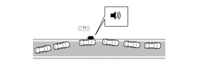
*1 Warning
-
-
Function Over View (Steering Assist Available)
-
If the system judges that the vehicle may deviate from the lane it is in, the system performs steering assist to help the driver correct the path of the vehicle. If the driver does not take appropriate action, the system sound a buzzer.
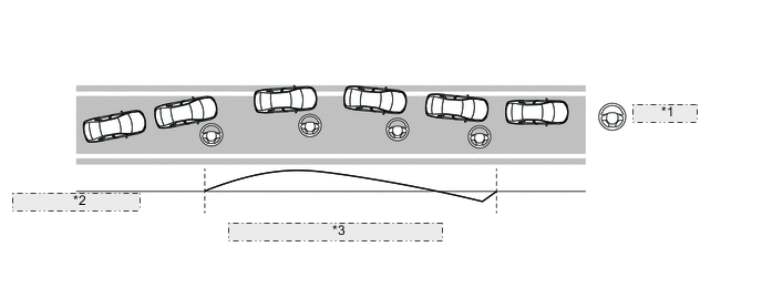
*1 Steering Assist *2 Control output level *3 Example of vehicle behavior and control output
-
-
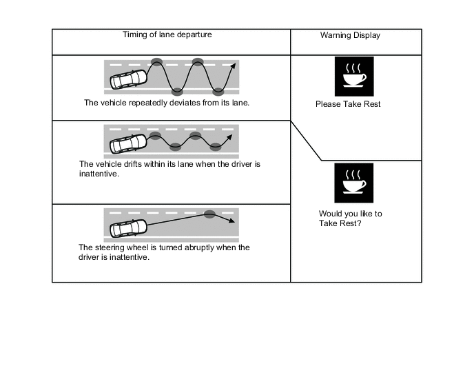
Function Over View (Vehicle Sway Warning)
-
The system detects drift of the vehicle within its lane, which is often the result of a driver who is tired, distracted or not looking ahead, based on the position of the vehicle within its lane and the steering inputs of the driver and alert the driver before a lane departure or collision occurs.
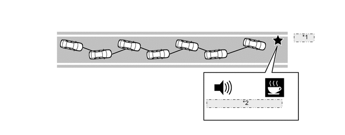
*1 Warning *2 Buzzer and Warning Display
-
-
-
-
FUNCTION
-
Using the Meter Control Switches of the steering pad switch assembly, the steering assist functions and the vehicle sway warning functions can be customized.
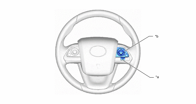
*a Lane departure Alert Main Switch (LDA Main Switch) *b Meter Control Switch -
Customize LDA system settings Functions
Item (Select using the up/down button of the meter control switch) Description Setting (Change using the center button of the meter control switch) Steering Assist Assists steering to prevent lane departure (steering wheel control)
-
ON
-
OFF
Warning Sensitivity Timing of lane departure alert
-
Standard
-
High
-
-
Customize Vehicle Sway Warning Functions
Item (Select using the up/down button of the meter control switch) Description Setting (Change using the center button of the meter control switch) Vehicle Sway Warning Vehicle sway warning function
-
ON
-
OFF
Vehicle Sway Detection Sensitivity Vehicle sway detection sensitivity
-
High
-
Standard
-
Low
-
-
The vehicle sway warning function provides a warning to alert the driver when any of the following conditions occur:
-
-
DIAGNOSIS
-
At the same time, the malfunction is stored in memory as a Diagnostic Trouble Code (DTC). When a Global TechStream (GTS) is connected to the DLC3, the DTC can be read. For details, refer to the Repair Manual.
-