SFI SYSTEM
-
CONSTRUCTION
-
A pick-up coil type crank position sensor is used. The timing rotor of the crankshaft consists of 34 teeth with 2 teeth missing. The crank position sensor outputs a crankshaft rotation signal every 10°, and the change in the signal due to the missing teeth is used to determine top-dead-center.
-
A Magneto-Resistance Element (MRE) type cam position sensor is used. To detect the camshaft position, a timing rotor that is part of the camshaft is used to generate 3 pulses (3 high output, 3 low output) for every 2 revolutions of the crankshaft.
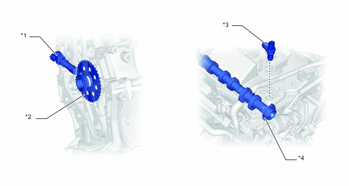
*1 Crank Position Sensor *2 Crankshaft Timing Sprocket *3 Cam Position Sensor *4 Timing Rotor Figure 1. Sensor Output Waveforms
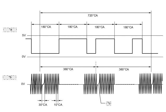
*a Cam Position Sensor Signal *b Crank Position Sensor Signal *c 2 Teeth Missing -
The MRE type sensor consists of a magnet and a sensor with a built-in MRE. The direction of the magnetic field changes due to the profile (protruding and non-protruding portions) of the timing rotor, which passes by the sensor. As a result, the resistance of the MRE changes, and the output voltage to the ECM changes to either high or low. The ECM detects the cam position based on this output voltage.
-
The differences between an MRE type sensor and a conventional pick-up coil type sensor are as follows.
Sensor Type MRE Pick-up Coil Signal Output Constant digital output starts from low engine speeds. Analog output changes with the engine speeds. Crankshaft Position and Camshaft Position Detection
-
Detected by comparing the NE signals with the switching of the high/low output that results from the protruding and non-protruding portions of the timing rotor.
-
Can also be detected based on the number of NE signals input during high/low outputs.
Detected by comparing the NE signals with the change of waveform that is output when the protruding portion of the timing rotor passes. 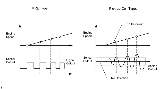
-
-