HYBRID CONTROL SYSTEM
-
CONSTRUCTION
-
A compact, lightweight inverter with converter assembly, in which the MG ECU, inverter, boost converter and DC-DC converter are integrated, is used. The inverter and boost converter primarily consist of Intelligent Power Modules (IPMs), a reactor, and capacitor. The IPM is an integrated power module consisting of a signal processor, protective function processor, and Insulated Gate Bipolar Transistors (IGBTs).
-
The inverter with converter assembly ensures heat dissipation through use of a water-cooled cooling system that is isolated from the engine cooling system.
-
As a safety measure due to the use of high-voltage electricity, interlock switches are provided, which shut off the system main relays via the hybrid vehicle control ECU when the inverter terminal cover or connector cover assembly is removed, or the HV battery power cable connector is disconnected.
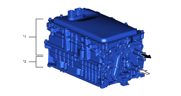
*1 Boost Converter / Inverter *2 DC-DC Converter 
HV Coolant Outlet 
HV Coolant Inlet -
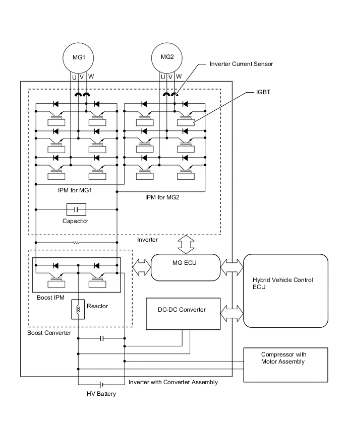
The inverter uses the IPM to perform switching control. The IPMs for generator (MG1) and motor (MG2) each have a bridge circuit consisting of IGBTs. The IPM for generator (MG1) uses 6 IGBTs, one for each arm, and motor (MG2) uses 6 pairs of IGBTs, single in parallel for each arm.
-
The boost converter uses a boost IPM to perform switching control, a reactor to act as an inductor, and a capacitor to accumulate and store electricity. The boost IPM uses IGBT2 for boosting voltage, and IGBT1 for reducing voltage.
-
MG ECU
-
The MG ECU is provided in the inverter with converter assembly. In accordance with the signals received from the hybrid vehicle control ECU, the MG ECU controls the inverter and boost converter in order to drive generator (MG1) or motor (MG2) or cause them to generate electricity.
-
The MG ECU transmits information that is required for vehicle control, such as the atmospheric pressure, inverter temperature and any failure information, to the hybrid vehicle control ECU. The MG ECU receives information that is required for controlling generator (MG1) and motor (MG2), such as the required motive force and the temperature of generator (MG1) and motor (MG2), from the hybrid vehicle control ECU.
-
-
Temperature Sensor for Inverter with Converter Assembly
-
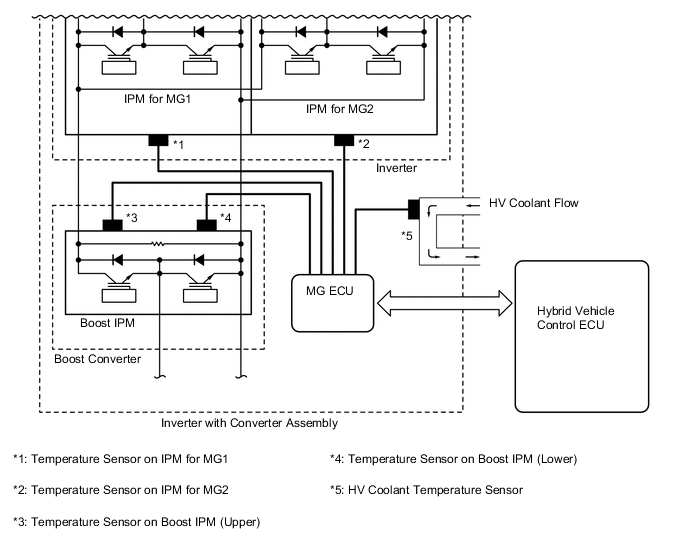
For the inverter with converter assembly, there are 5 different temperature sensors; 2 of them are located at the IPMs for generator (MG1) and motor (MG2), 2 of them are located at the boost converter, and the remaining sensor is located at the HV coolant passage.
-
These sensors detect the temperatures at areas inside the inverter with converter assembly, and transmit that temperature information to the hybrid vehicle control ECU via the MG ECU. The hybrid vehicle control ECU optimizes the cooling system according to the temperature information, maintaining the output performance of the inverter with converter assembly.
-
-
Inverter Current Sensor
-
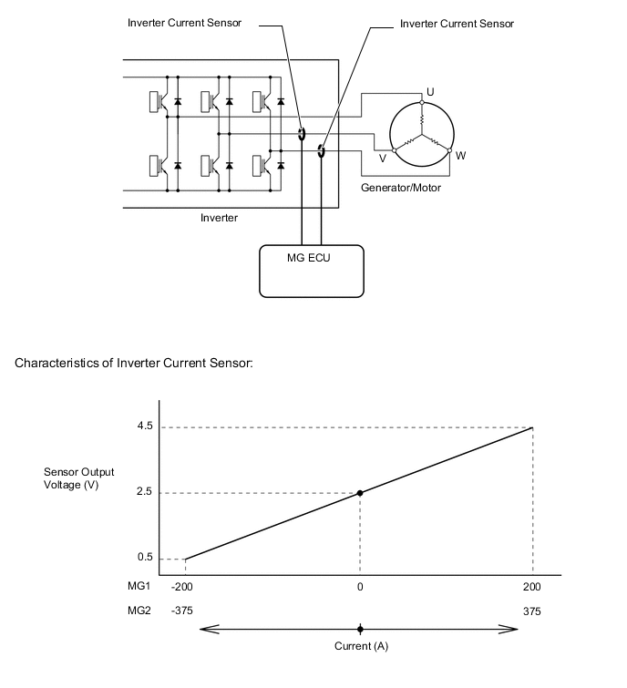
The inverter current sensors detect the amperage of the three-phase alternating current that actuates generator (MG1) and motor (MG2). This actual amperage is used as feedback by the MG ECU.
-
Current sensors are used for the current sent to the three-phase windings of generator (MG1) and motor (MG2). The current sensors are located in the inverter with converter assembly for the U, V and W phases of each generator and motor.
-
-