HYBRID CONTROL SYSTEM
-
CONSTRUCTION
-
The inverter converts the boosted high-voltage direct current of the HV battery into 3-phase alternating current to drive MG1 and MG2.
-
The activation of the power transistors is controlled by the Motor Generator ECU (MG ECU). In addition, the inverter transmits information that is needed for current control, such as the output amperage or voltage, to the hybrid vehicle control ECU via the MG ECU.
-
The power transistors used in the inverter are Insulated Gate Bipolar Transistors (IGBTs).
-
Each of the bridge circuits for MG1 and MG2 contains 6 IGBTs, mounted on the high voltage and high current module portion of an Intelligent Power Module (IPM). In addition, a signal processor/protective function processor has been integrated into the control portion of the IPM. The IPM is used to operate the power transistors based on signals from the MG ECU.
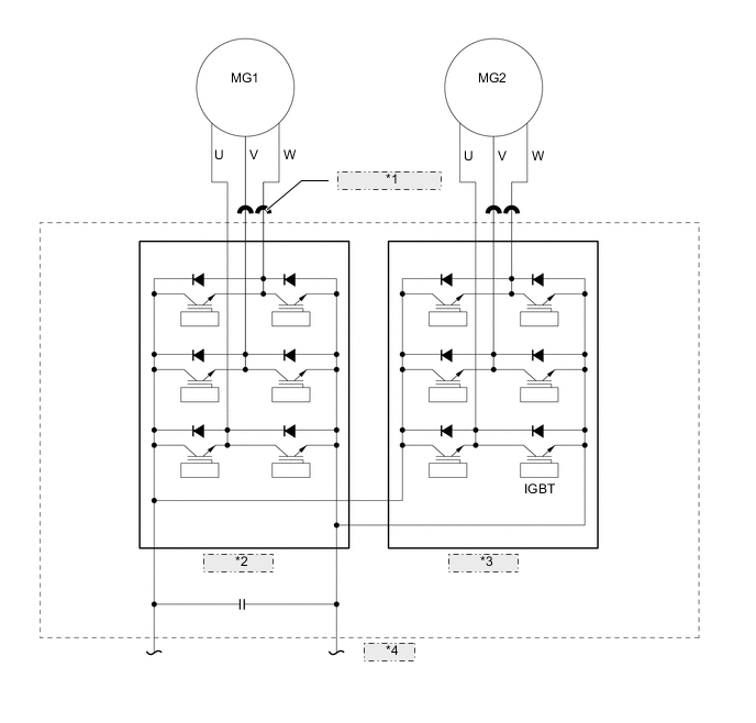
*1 Inverter Current Sensor *2 IPM for MG1 *3 IPM for MG2 *4 Inverter
-