AUTOMATIC TRANSAXLE SYSTEM
-
CONSTRUCTION
-
A shift control mechanism with a push-pull type transmission cable assembly is used.
-
A gate type shift lever, which is installed on the instrument panel, is provided. Additionally, a transmission control switch, which allows a desired shift range to be selected by moving the shift lever toward "+" (upshift) or "-" (downshift), is provided, enabling the driver to select shift ranges with a manual-like feel.
-
A shift lock release button is provided inside the shift lever housing in consideration of emergency situations.
Figure 1. LHD Models
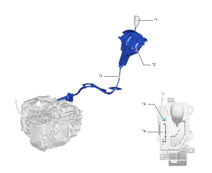
*1 Shift Lever Knob Sub-assembly *2 Shift Lever Assembly (Shift Lock Control Unit Assembly) *3 Transmission Control Cable Assembly *4 Shift Lock Release Button Cover *a Shift Pattern - - Figure 2. RHD Models
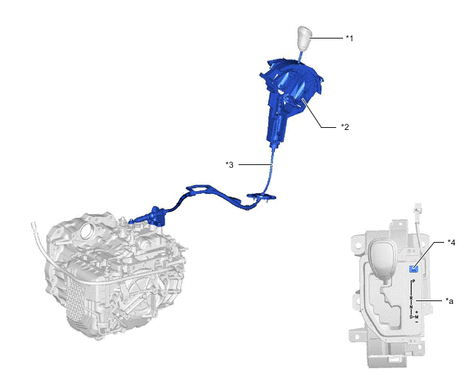
*1 Shift Lever Knob Sub-assembly *2 Shift Lever Assembly (Shift Lock Control Unit Assembly) *3 Transmission Control Cable Assembly *4 Shift Lock Release Button Cover *a Shift Pattern - -
-