AUTOMATIC TRANSAXLE SYSTEM
-
FUNCTION OF MAIN COMPONENTS
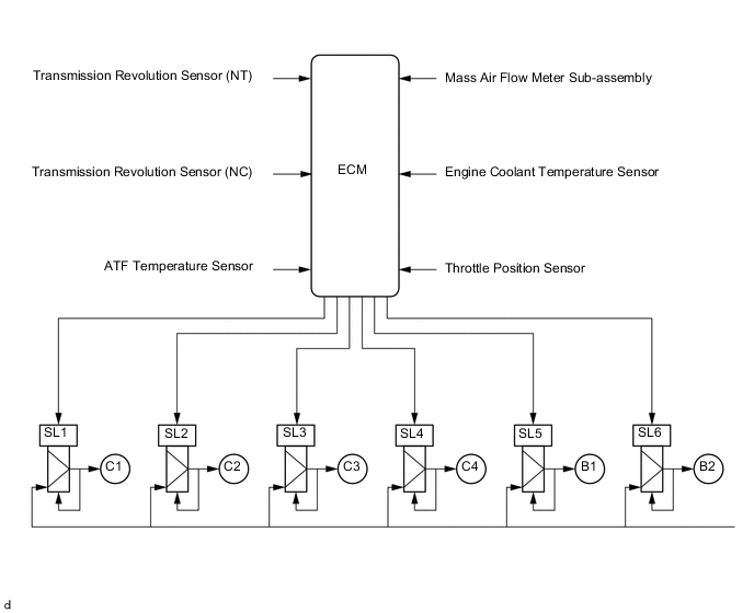
Component Function Shift Solenoid Valve SL1 Controls the No. 1 clutch (C1) pressure. Shift Solenoid Valve SL2 Controls the No. 2 clutch (C2) pressure. Shift Solenoid Valve SL3 Controls the No. 3 clutch (C3) pressure. Shift Solenoid Valve SL4 Controls the No. 4 clutch (C4) pressure. Shift Solenoid Valve SL5 Controls the No. 1 brake (B1) pressure. Shift Solenoid Valve SL6 Controls the No. 2 brake (B2) pressure. Shift Solenoid Valve SLT (Line Pressure Control Solenoid Assembly)
-
Controls line pressure.
-
Switches the sequence valve.
Shift Solenoid Valve SLU (Lock-up Control Solenoid Assembly)
-
Controls the lock-up clutch pressure.
-
Switches the pressure relay valve.
Shift Solenoid Valve SL Switches the lock-up relay valve. Transmission Revolution Sensor (NT) Detects the input speed of the transaxle. Transmission Revolution Sensor (NC) Detects the speed of the counter gear. ATF Temperature Sensor (Transmission Wire) Detects the ATF temperature. Accelerator Pedal Sensor Assembly Detects the accelerator pedal opening angle. Throttle Body with Motor Assembly Throttle Position Sensor Detects the throttle valve opening angle. Mass Air Flow Meter Sub-assembly Air Flow Meter Detects the intake air volume and intake air temperature. Intake Air Temperature Sensor Crank Position Sensor Detects the engine speed and performs the cylinder identification. Engine Coolant Temperature Sensor Detects the engine coolant temperature. Park/Neutral Position Switch Assembly Detects the shift lever position. Shift Lever Assembly (Shift Lock Control Unit Assembly) Transmission Control Switch
-
Detects when the shift lever is in M.
-
Detects the shift-up and shift-down operations performed by the driver when the shift lever is in M.
Combination Switch Assembly ECO Mode Switch Sends the ECO mode switch operation signal to the airconditioning amplifier assembly. Stop Light Switch Assembly Detects when the brake pedal is depressed. ECM
-
Controls engine output and each shift solenoid valve in response to a signal from each sensor and switch.
-
Makes a diagnosis and memorizes the failed section when the ECM detects a malfunction.
Air Conditioning Amplifier Assembly Transmits various air conditioning state signals to the ECM. Airbag ECU Assembly Yawrate Sensor
-
Detects the vehicle's longitudinal and lateral acceleration.
-
Detects the vehicle's yaw rate.
Acceleration Sensor Combination Meter Assembly Malfunction Indicator Lamp (MIL) Illuminates to inform the driver when the ECM detects a malfunction. Multi-information Display
-
Displays the shift lever position.
-
Displays the shift range.
-
Displays the ECO mode.
Buzzer Sounds when the shift-down operation is rejected. Oil Pump with Solenoid Assembly Holds the AT oil pressure during idle stop. -
-
SYSTEM CONTROL
-
The electronic control system of the UA80E automatic transaxle uses the controls listed below.
Control Outline Shift Timing Control The ECM sends current to shift solenoid valves SL1, SL2, SL3, SL4, SL5, SL6, and/or SLU, based on signals from various sensors, in order to shift the gears. Powertrain Cooperative Control Controls both shift control and engine output control in an integrated way, achieving excellent shift characteristics and driveability. Clutch Pressure Control The shift solenoid valve minutely control the clutchpressure in accordance with the engine output and driving conditions of the transaxle. Clutch to Clutch Pressure Control
-
Controls the pressure that is applied directly to the C1, C2, C3, C4 clutches and B1, B2 brakes by actuating the shift solenoid valves (SL1, SL2, SL3, SL4, SL5 and SL6) in accordance with signals from the ECM.
-
The solenoid valves SLT, SLU, SL, SL1, SL2, SL3, SL4, SL5 and SL6 precisely control the clutch pressure in accordance with the engine output and driving conditions.
Line Pressure Control Actuates shift solenoid valve SLT to control the line pressure in accordance with information from the ECM and the operating conditions of the transaxle. Lock-up Control The ECM sends current to shift solenoid valves SL and SLU based on signals from various sensors to engage or disengage the lock-up clutch. Flex Lock-up Clutch Control Controls the shift solenoid valve SLU, provides an intermediate mode between the on and off states of the lock-up clutch, and increases the operating range of the lock-up clutch to improve fuel economy. Flex Start Control Operates the lock-up clutch frequently when starting off to achieve increased fuel economy. Deceleration Downshift Control To prevent engine speed from decreasing and thereby maintain fuel cut, the ECM performs downshifts before fuel cut ends. Direct Connected Downshift When the accelerator pedal is depressed, the vehicle downshifts smoothly through the intermediate gears to the selected gear, without delay of drive force or engine speed increase. Artificial Intelligence Shift Control (AI-shift Control) Based on the signals from various sensors, the ECM determines the road conditions and the intention of the driver. Thus, an appropriate shift pattern is automatically determined, improving driveability. Multi-mode Automatic Transmission When the shift lever is moved to M, driving in a gear position selected using the shift lever is enabled. Fail-safe If a malfunction is detected in the sensors or solenoids, the ECM performs fail-safe control to prevent vehicle driveability from being significantly affected. Diagnosis When the ECM detects a malfunction, the ECM records the malfunction and memorizes the information that relates to the fault. -
-
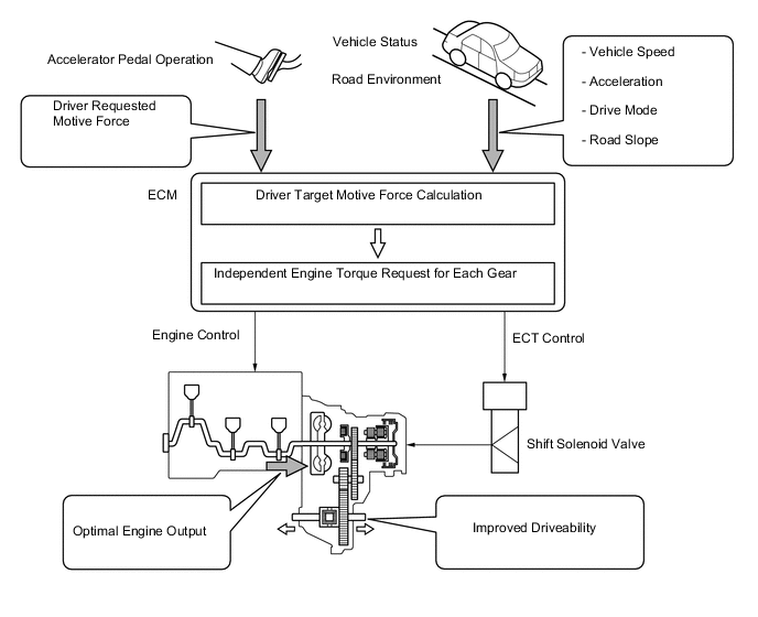
Powertrain Cooperative Control
-
Previous driving force characteristics were dependent on the torque characteristics of the engine electronic throttle opening angle and the gear ratio at each gear speed level. To achieve the driver's target driving force, the new control system uses an independent engine torque request for each gear, realizing increased fuel efficiency and driveability.
-
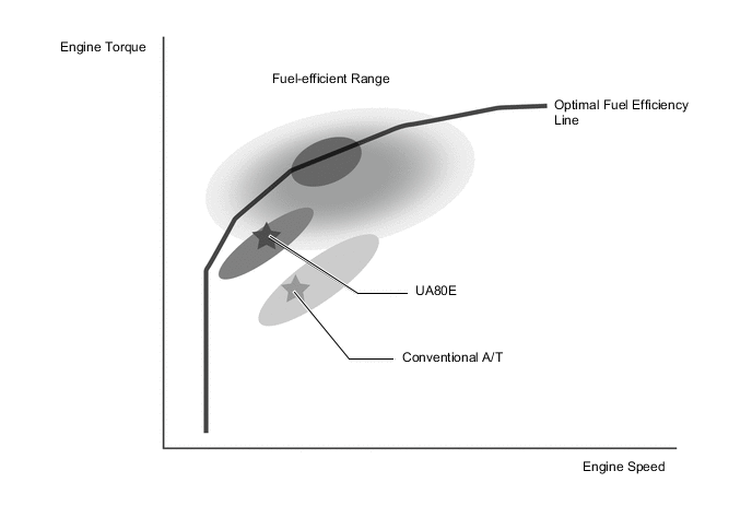
At low accelerator opening angles, the highly efficient low engine speed ranges are aggressively employed, contributing to improved fuel efficiency and reduced noise.
-
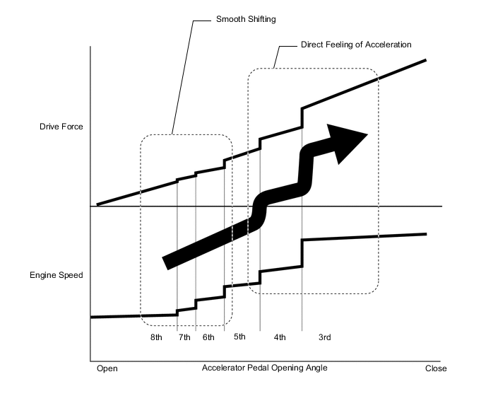
At low accelerator opening angle ranges, highly efficient engine ranges are aggressively employed, realizing increased fuel efficiency. At the same time the differences between target driving forces at each gear level are small, enabling smooth downshift without noticeable driving force change.
-
When the accelerator is deeply depressed to accelerate, the target driving force is set to be directly linked to the engine speed change, resulting in a direct and energetic feeling of acceleration, with the goal of achieving high balance of fuel efficiency and driveability.
-
-
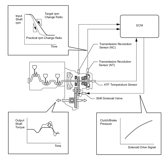
Clutch Pressure Control
-
The ECM monitors the signals from various types of sensors, such as the transmission revolution sensor (NT) and transmission revolution sensor (NC), allowing the linear solenoid valves SLT, SL1, SL2, SL3, SL4, SL5, SL6 and SLU to precisely control the clutch pressure in accordance with engine output and driving conditions. As a result, the transmission has smooth shift characteristics.
-
-
Clutch-to-Clutch Pressure Control
-
Clutch-to-Clutch pressure control is used for shift control. As a result, shift control in 2nd gear or above is possible without using a one-way clutch, making the automatic transaxle lightweight and compact.
-
Using the fluid pressure circuit, which enables the clutches and brakes (C1, C2, C3, C4, B1 and B2) to be controlled independently, and the high flow SL1, SL2, SL3, SL4, SL5, and SL6 linear solenoid valves, which directly control the clutch pressure, the ECM controls each clutch and brake accordingly with the optimum fluid pressures and timings in accordance with the information transmitted by the sensors, and then shifts the gears. As a result, the transmission has highly responsive and excellent shift characteristics.
-
-
Line Pressure Control
-
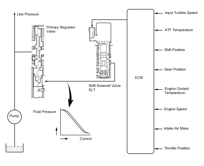
The line pressure is controlled using shift solenoid valve SLT.
-
Through the use of shift solenoid valve SLT, the line pressure is optimally controlled in accordance with the engine torque information, as well as with the internal operating conditions of the torque converter clutch assembly and the automatic transaxle assembly.
-
Accordingly, the line pressure can be accurately controlled in accordance with the engine output, traveling condition, and the ATF temperature, thus realizing smooth shift characteristics and optimizing the workload of the oil pump (reducing parasitic losses).
-
-
All Range Lock-up
-
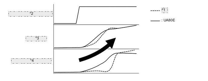
Compared to the previous model, the UA80E performs lock-up control at lower speeds as well as at higher opening angles, enabling direct transmission of power similar to a manual transmission. Furthermore, the increased rate of engagement contributes to improved fuel efficiency.
-
By increasing the lock-up range, and suppressing engine revving, smooth driving with high responsiveness and linearity is realized.
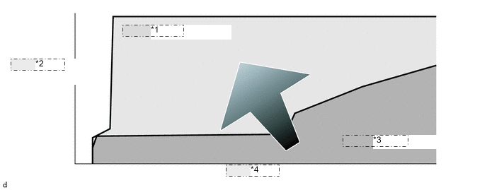
*1 UA80E L/U Range *2 Accelerator Pedal Angle *3 Conventional A/T *4 Vehicle Speed 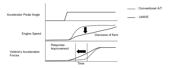
-
Previously, lock-up was cancelled when downshifting to avoid shift shock, but with a torque converter adopting a multiple disc lock-up clutch as well as precision control taking into account transient characteristics of engine torque and hydraulic pressure, it has become possible to maintain lock-up continuously.
-
In 1st gear and the low engine speed regions of 2nd and higher gears, lock-up is not performed, and the torque converter function is employed to realize smooth driving.
Gear Position Shift Lever Position D, M 1st X 2nd ○*(During acceleration) 3rd ○* 4th ○* 5th ○* 6th ○* 7th ○* 8th ○* ○: Operates
X: Does not operate
*: Except at low engine speed range
-
-
Flex Lock-up Clutch Control
-
During acceleration, partial control of the power transmission between the lock-up clutch and torque converter greatly boosts transmission efficiency in accordance with the driving conditions, improving fuel economy.
-
Even when the vehicle is decelerating (the accelerator pedal is released), flex lock-up clutch control operates. As a result, the fuel-cut area is expanded and fuel economy is improved.
-
By allowing flex lock-up clutch control to continue operating during gearshifts, smooth torque transmission is obtained. As a result, fuel economy and driveability are improved.
-
For flex lock-up clutch control, H infinity (H∞) control theory is used to achieve a high level of system stability and response to various characteristic changes.
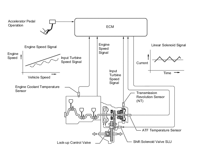
Figure 1. Flex Lock-up Operating Range
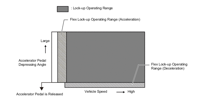
Flex Lock-up Clutch Control Operation Gear Position Shift Range D, M 1st X 2nd ○ 3rd ○ 4th ○* 5th ○* 6th ○* 7th ○* 8th ○* ○: Operates
X: Does not operate
*: Flex lock-up clutch control also operates when the vehicle decelerates.
-
-
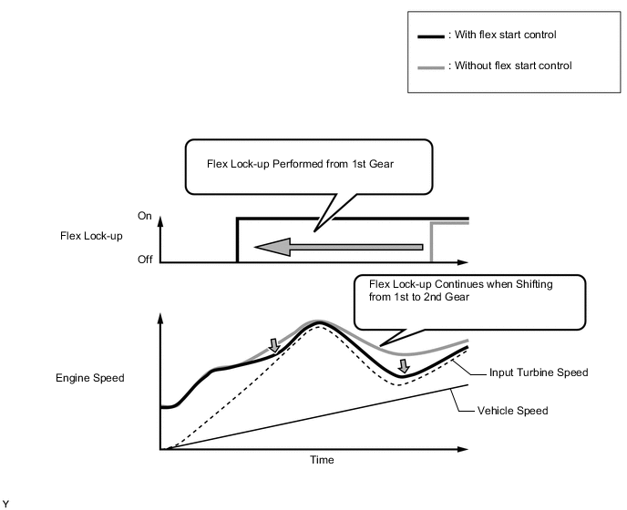
Flex Start Control
-
Flex start control suppresses unnecessary engine speed increases to achieve improved fuel economy.
-
When starting off, the lock-up clutch operates frequently to improve power transmission efficiency, making it possible to decrease the engine speed.
-
Also, since flex lock-up can be quickly performed even after upshifting to the 2nd gear due to flex lock-up being performed when starting off, driveability and improved fuel economy are achieved.
-
-
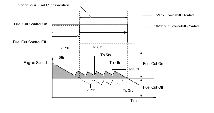
Deceleration Downshift Control
-
The ECM performs downshift control to help prevent the engine speed from decreasing, thus keeping fuel cut control operating for as long as possible. In this way, fuel economy is improved.
-
In this control, the transmission downshifts from 7th to 3rd before fuel cut control ends when the vehicle is decelerated in the 8th gear, so that fuel cut control continues operating.
-
-
Direct Connected Downshift
-
Smooth vehicle acceleration changes and linear changes in engine speed during downshifting were realized.
-
By precisely controlling hydraulic pressure, downshifting from a high gear to a low gear is accomplished with a smooth shift through the intermediate gears without any unevenness of engine speed or drive force.
*1 Conventional A/T *2 Accelerator Pedal Angle *3 Engine Speed *4 Vehicle's Acceleration Forces
-
-
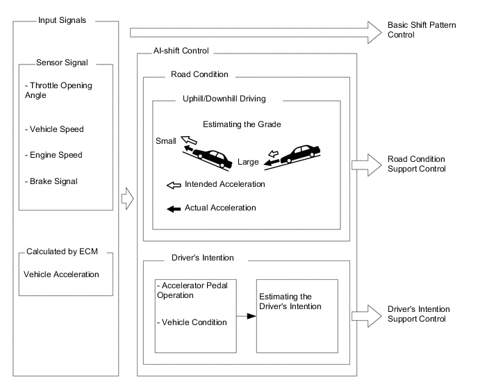
Artificial Intelligence Shift Control (AI-shift Control)
-
The automatic transaxle gear is determined by the shift pattern, which uses the vehicle speed and throttle valve opening angle.
-
Additionally, AI-shift control enables the ECM to estimate the road conditions and the driver's intention in order to automatically control the shift pattern in the optimal manner. As a result, a comfortable ride has been achieved.
-
The AI-shift control includes road condition support control and driver's intention support control.
-
The AI-shift control determines optimal transaxle control based on input signals and automatically changes the shift pattern.
-
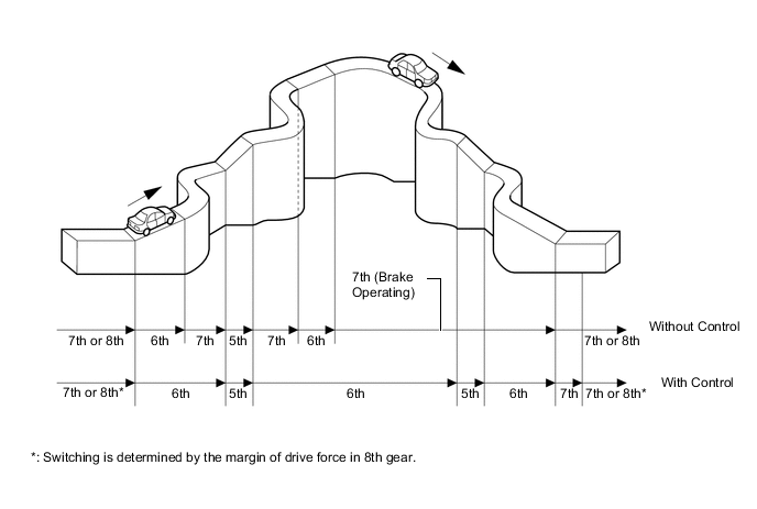
Under road condition support control, the ECM determines the throttle opening angle and the vehicle speed in addition to whether the vehicle is being driven uphill or downhill. To achieve optimal drive force while driving uphill, this control prevents unnecessary upshifts. To achieve the optimal engine braking while driving downhill, this control automatically performs downshifts.
-
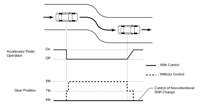
Driver's Intention Support Control
-
The driver's intention is estimated based on the accelerator pedal depression angle and vehicle condition to switch to a shift pattern that is well-suited to the driver.
-
-
Driver Intention/Driving Scene Support Control
-
Driver intention/driving scene support control selects the optimal gear position according to the driver's intentions and the driving scene at that point in time.
-
When the driver is driving in a relaxed manner, a high gear position is selected to emphasize fuel efficiency.
-
When the driver is driving in a sporty manner, a low gear position is selected to emphasize drive force and responsiveness.
-
Even if the driver has the D range selected while sporty driving is performed on winding roads and race tracks, shifting is performed using a shift pattern that makes it feel like gear positions are being selected manually, achieving a high-speed responsive drive.
Tech Tips
Driver intention/driving scene support control will be canceled when Eco mode is selected.
-
-
-
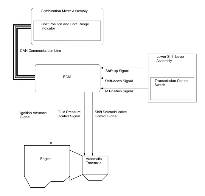
Multi-mode Automatic Transmission
-
When the shift lever is moved to M, the system changes from automatic shift control to M mode control, where the driver can manually change the gear position by moving the shift lever to the "+" (upshift) and "-" (downshift) sides.
-
When the vehicle is being driven at a speed that is higher than the maximum safe speed for a downshift, any attempt to shift to a lower range by operating the shift lever will not be performed. This is done in order to protect the automatic transaxle. In this case, the ECM sounds the buzzer in the combination meter assembly twice to alert the driver.
-
Under this control, the ECM performs optimal shift control within the usable gear range that the driver selects. As with an ordinary automatic transaxle, it shifts to 1st gear when the vehicle is stopped.
-
The shift lever position and the shift range are indicated by the shift position indicator in the combination meter assembly (The shift range is shown only when the M mode control).
-
In order to prevent excessive engine speed, a function was adopted that automatically selects a higher shift range before engine speed becomes too high.
-
In order to protect the automatic transmission, a function is adopted that automatically selects a higher shift range when the fluid temperature is high.
Usable Gear Chart: Shift Range Shift Position Indicator Usable Gear M8 8 8th M7 7 7th M6 6 6th M5 5 5th M4 4 4th M3 3 3rd M2 2 2nd M1 1 1st -
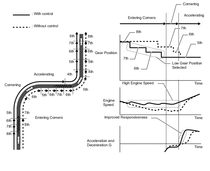
Gear Hold Control
-
Gear shifting will not be performed under gear hold control as long as the shift lever is not operated. This makes it possible to make efficient use of the highest engine speeds. However, in the following cases, operation of gear hold control is limited.
-
When the vehicle speed and engine speed decrease, a downshift is performed.
-
When the engine speed reaches the red zone, an automatic upshift is performed.
-
When the ATF temperature is high, gear shifting will be performed automatically.
-
When the ATF or engine coolant temperature is low, gear shifting will be performed automatically.
-
-
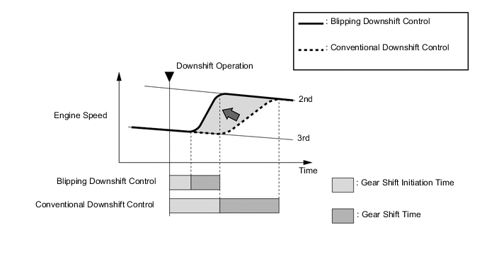
Blipping Downshift Control
-
The blipping downshift control regulates each clutch and brake using the clutch to clutch pressure control, allowing them to be engaged smoothly and disengaged quickly. In addition, fuel injection volume is increased and engine speed is boosted by the powertrain cooperative control, thus ensuring proper engine brake force. In this way, a smooth and quick downshift is achieved.
-
The blipping downshift control activates by downshifting with the shift lever in D or M.
Figure 2. Downshift from 3rd to 2nd Gear
-
-
-
-
FUNCTION
-
ECO Mode
-
When ECO mode is turned on, the ECO mode indicator on the combination meter assembly will illuminate.
-
ECO mode changes the transmission characteristics to ones which prioritize fuel efficient driving to ensure low fuel consumption compared to those of NORMAL mode. This drive mode provides optimal fuel efficiency.
-
-
-
FAIL-SAFE
-
The fail-safe function minimizes the loss of operability when an abnormality occurs in a sensor or a shift solenoid valve.
-
For details, refer to the Repair Manual.
-
-
DIAGNOSIS
-
When the ECM detects a malfunction, the ECM records the malfunction and memorizes the information related to the fault. Furthermore, the ECM illuminates the Malfunction Indicator Lamp (MIL) in the combination meter assembly to inform the driver.
-
The ECM will also store Diagnostic Trouble Codes (DTCs) of the malfunctions. The DTCs stored in the ECM are output to the Global TechStream (GTS) via the DLC3.
-
For details, refer to the Repair Manual.
-