SFI SYSTEM
-
CONSTRUCTION
-
The mass air flow meter sub-assembly, which is slot-in type, allows portion of the intake air to flow through the detection area.
-
This mass air flow meter sub-assembly has built-in intake air temperature sensors.
-
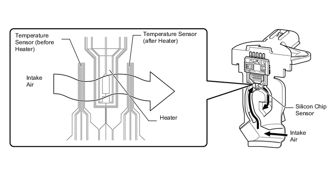
Intake air flows over the temperature sensor (before heater), the heater, and then the temperature sensor (after heater) on the silicon chip sensor in the by-pass passage. As the intake air is warmed up when it is exposed to the heater, the temperature of the intake air flowing over the temperature sensor (after heater) is higher than that over the temperature sensor (before heater). The difference in temperature of the intake air at each temperature sensor varies depending on the velocity of the intake air that flows over the silicon chip sensor. The temperature sensor bridge circuit detects the difference in temperature and the control circuit converts it into a pulse signal and outputs it to the ECM. When the temperature detected by the temperature sensor (before heater) is higher than that detected by the temperature sensor (after heater), backflow of the intake air is detected.
-
The ECM calculates the intake air amount based on the pulse signal received from the mass air flow meter sub-assembly, and uses it to determine the fuel injection duration necessary for an optimal air-fuel ratio.
-
The heater control bridge circuit includes temperature sensors and power transistor, and maintains the heater temperature at a specific temperature.
Tech Tips
When either of these DTCs is stored, the ECM enters fail-safe mode. During fail-safe mode, the ECM calculates the fuel injection duration based on the engine speed and throttle valve angle. Fail-safe mode continues until a pass condition is detected. For details, refer to the Repair Manual.
-