BODY STRUCTURE
-
CONSTRUCTION
-
Body Shell
-
The position of the body's structural parts is optimized and reinforcing materials are provided, creating a body structure with high rigidity and ensuring driving stability.
-
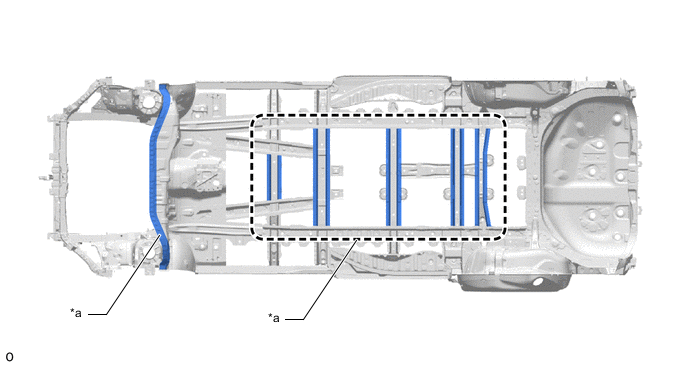
A straight ladder structure that passes through the floor side members from the rear portion of the dash panel to the rear portion of the rear wheel house is used to ensure torsional rigidity of the floor.
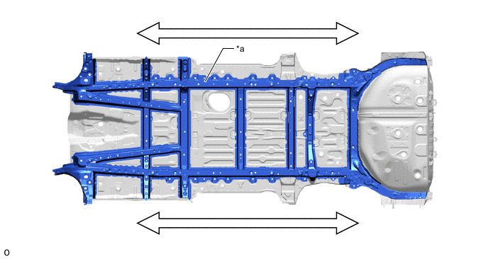
*a Straight Ladder Structure - - -
A high-rigidity rear suspension member sub-assembly (*5 in illustration) is provided, ensuring superior driving stability and riding comfort.
-
Driving stability braces (front floor brace (*1 and *2 in illustration), rear suspension member stopper lower (*3 and *4 in illustration)) are provided in the installation area around the rear suspension member sub-assembly (*5 in illustration), suppressing body deformation and ensuring driving stability.
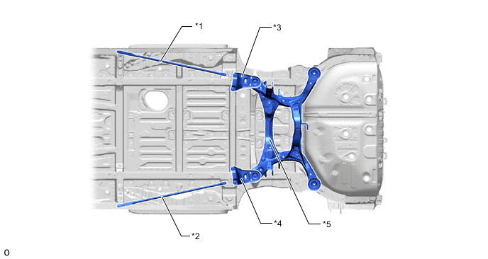
*1 Front Floor Brace LH *2 Front Floor Brace RH *3 Rear Suspension Member Stopper Lower LH *4 Rear Suspension Member Stopper Lower RH *5 Rear Suspension Member Sub-assembly - - -
The area around the corners of the door opening uses the following optimal structures, ensuring rigidity of the sliding door opening.
-
The center body pillar reinforcement UPR (*1 in illustration) and center body pillar inner UPR (*2 in illustration) are extended to the corners, restraining cross-sectional collapse.
-
The ridge lines of the reinforcements run through the T-shaped section, suppressing cross sectional collapse.
-
The side panel outer (*4 in illustration) and rocker panel reinforcement No. 3 (*5 in illustration) are connected, restraining cross-sectional collapse.
-
The lower portion of the quarter lock pillar lower outer (*6 in illustration) and lower portion of the side panel outer (*4 in illustration) are spot welded together, and the No. 3 lower rail plate inner (*7 in illustration) is spot welded to the quarter wheel house panel outer (*8 in illustration) and roof side panel inner lower (*9 in illustration). This prevents bending deformation vertically throughout the quarter lock pillar.
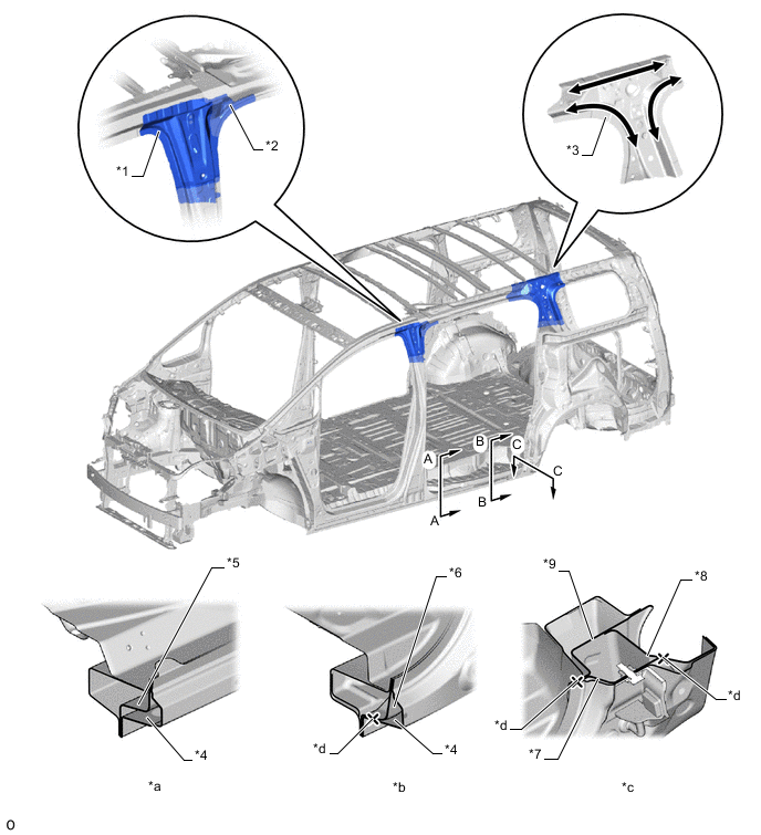
*1 Center Body Pillar Reinforcement UPR *2 Center Body Pillar Inner UPR *3 Quarter Lock Pillar Reinforcement UPR *4 Side Panel Outer *5 Rocker Panel Reinforcement No. 3 *6 Lower Section of Quarter Lock Pillar Lower Outer *7 No. 3 Lower Rail Plate Inner *8 Quarter Wheel House Panel Outer *9 Roof Side Panel Inner Lower - - *a A - A Cross Section *b B - B Cross Section *c C - C Cross Section *d Spot Welding -
Reinforcements (quarter wheelhouse reinforcement inner rear (*2 in illustration) and rear suspension spring support (*1 in illustration)) are provided in the rear wheelhouse, ensuring high rigidity at the load point for input from the rear suspension (*d in illustration), restraining bending and achieving superior driving stability performance.
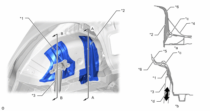
*1 Rear Suspension Spring Support *2 Quarter Wheel House Reinforcement Inner Rear *3 Rear Suspension *4 Rear Floor Panel Reinforcement No. 2 *5 Rear Seat Leg Bracket No. 1 *6 Quarter Wheel House Panel Inner *a A - A Cross Section *b B - B Cross Section *c Bending Restraint *d Input Load from Rear Suspension -
The entire circumference of the back door opening is connected using a continuous closed cross section to ensure the rigidity of the back door opening.
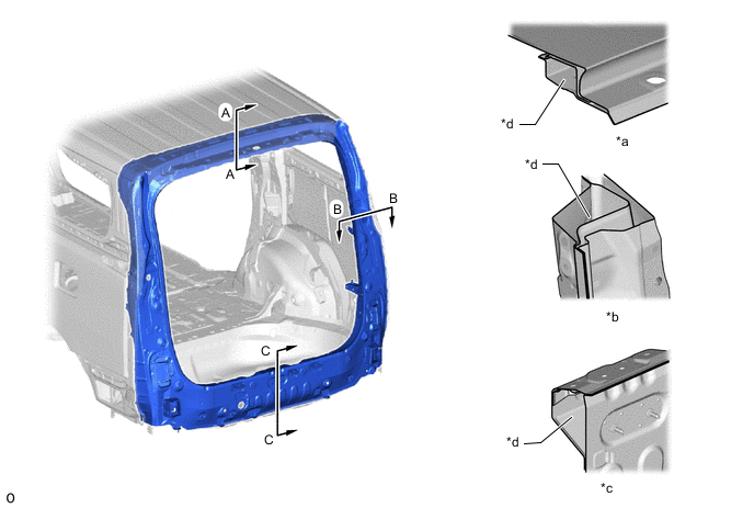
*a A - A Cross Section *b B - B Cross Section *c C - C Cross Section *d Closed Cross Section
-
-
-
Spot Welding
-
An increased number of spot welding points are provided throughout the body, increasing the connectivity of the panels and ensuring superior driving stability (steering response and hand feedback).
-
Numerous spot welding points are concentrated in areas that will effectively increase body rigidity such as the floor member and the connecting portion of the dash panel and cowl top inner panel to ensure superior riding comfort.
*a Increased Number of Spot Welding Points - - -
Numerous spot welding points are used around the openings of the front door, sliding door and back door in an effort to improve the rear grip feeling and ensure superior driving stability.
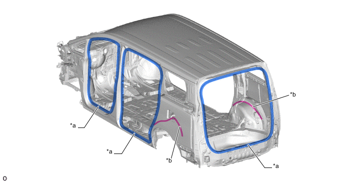
*a Increased Number of Spot Welding Points *b Adhered
-
-
-
Lightweight Solution
-
The structure and materials of the body have been optimized, achieving a lightweight body and ensuring driving stability.
-
The drive method of the electric sliding door uses a position in the step (belt drive (*6 in illustration)). Also, the lower rail (*b in illustration) and motor unit bracket (power slide doorstep assembly: *5 in illustration) are made of resin and integrated with the slide door motor unit (*1 in illustration), reducing the weight of the drive unit of the electric sliding door.
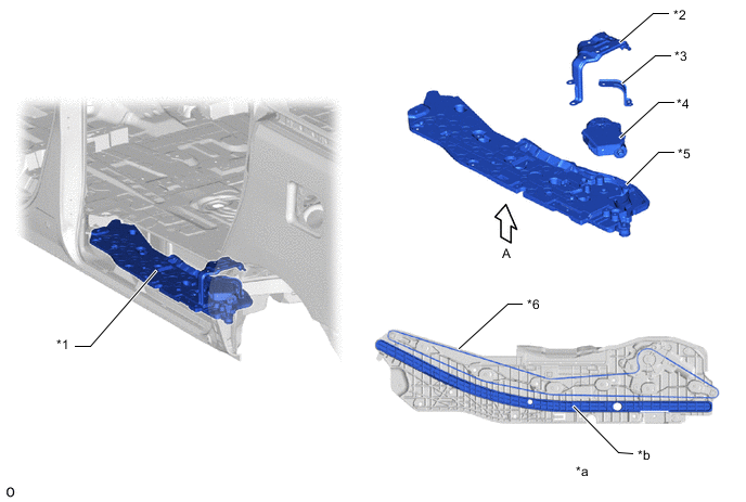
*1 Slide Door Motor Unit *2 Side Step Support Rear *3 Power Slide Door Bracket *4 Power Slide Door Actuator Assembly *5 Power Slide Door Step Assembly *6 Power Slide Door Motor Belt *a View from A *b Lower Rail -
The front fender panel (*1 in illustration), front door panel outer (*2 in illustration), slide door panel outer (*3 in illustration), back door panel outside (*4 in illustration) and roof panel (*5 in illustration) have an optimally placed cross-sectional shape in the design surface and reinforcements, ensuring rigidity and consequently achieving a reduction in weight and panel thickness.
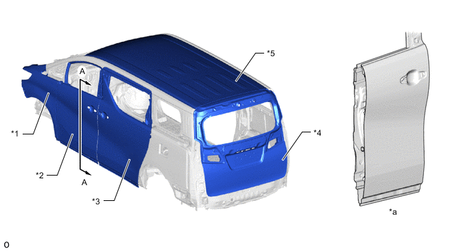
*1 Front Fender Panel *2 Front Door Panel Outer *3 Slide Door Panel Outer *4 Back Door Panel Outside *5 Roof Panel - - *a View from A - - -
Roof beads (*a in illustration) are provided in the roof panel (*1 in illustration), and reinforcements are optimally positioned to achieve roof panel (*1 in illustration) weight reduction while also ensuring rigidity strength. Also, for models with a normal roof, the positions of the roof beads are split, reducing muffled sounds that come from the roof panel (*1 in illustration).
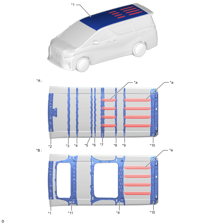
*A Models with Normal Roof *B Models with Sliding Roof *1 Roof Panel *2 Windshield Header Panel Inner *3 Roof Panel Reinforcement No. 1 *4 Roof Panel Reinforcement No. 2 *5 Roof Panel Reinforcement No. 3 *6 Roof Panel Reinforcement No. 4 *7 Roof Panel Reinforcement No. 5 *8 Roof Panel Reinforcement No. 6 *9 Roof Panel Reinforcement No. 7 *10 Back Door Opening Frame Sub-assembly Upper *11 Roof Panel Reinforcement Sub-assembly - - *a Roof Bead - -
-
-
-