BODY STRUCTURE
-
CONSTRUCTION
-
Aerodynamic Parts
-
Aerodynamic parts are provided on various parts of the vehicle and the Cd level* is reduced to achieve improved fuel efficiency.
Tech Tips
*: The Cd level refers to the air resistance coefficient. Cd stands for Constant drag. The lower the level is, the lesser the air resistance is. This improves fuel efficiency.
-
A front bumper absorber lower (*1 in illustration), engine under cover No. 1 (*2 in illustration), engine under cover No. 2 (*3 in illustration), front floor cover LH (*4 in illustration), front floor cover RH (*5 in illustration) and floor under cover No. 2 (*6 in illustration) are provided to reduce the Cd value (Cd: Constant drag, the air resistance coefficient), improving fuel economy.
-
The engine under cover seal No. 1 (*7 in illustration) is provided to reduce the Cd value and improve fuel economy.
-
Aero fins (*b in illustration) are provided to the engine under cover No. 1 (*2 in illustration), front floor cover LH (*4 in illustration) and front floor cover RH (*5 in illustration) to increase the airflow adjustment effect, ensuring superior driving stability performance.
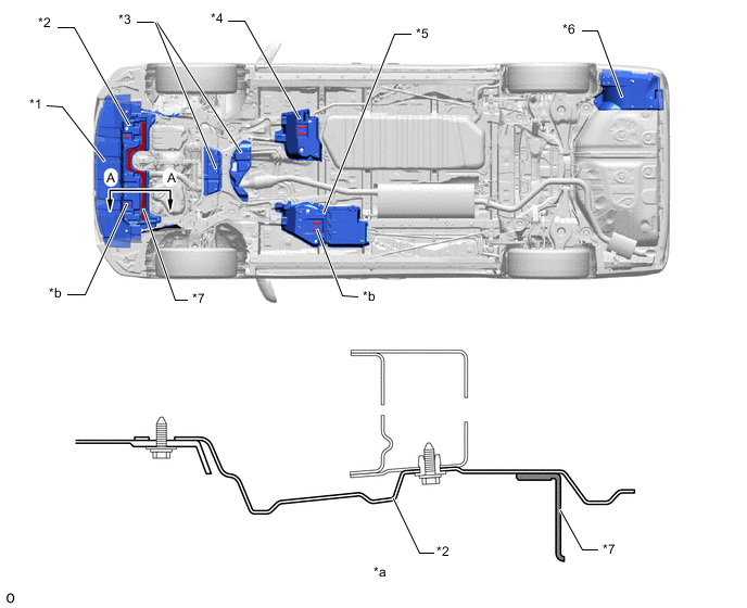
*1 Front Bumper Absorber Lower *2 Engine Under Cover No. 1 *3 Engine Under Cover No. 2 *4 Front Floor Cover LH *5 Front Floor Cover RH *6 Floor Under Cover No. 2 *7 Engine Under Cover Seal No. 1 - - *a A - A Cross Section *b Aero Fin -
The front wheel opening extension pad uses a "peaked shape" to restrain the air volume that contacts the rotating tire. As a result, disturbances due to air turbulence from the rotation of the front tire interfering with the air flow around it are suppressed and the air flow is adjusted to ensure a higher dimension of straightline stability when driving at high speeds while reducing air resistance.
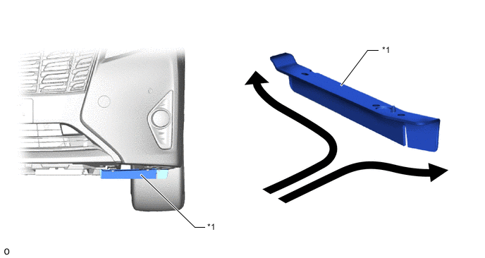
*1 Front Wheel Opening Extension Pad - - 
Air Flow - - -
A groove is provided in the front fender splash shield sub-assembly. As a result, airflow in the wheel housing is introduced to smoothly flow parallel to the tires to make it flow in the wheel housing smoothly, thus ensuring superior maneuver stability.
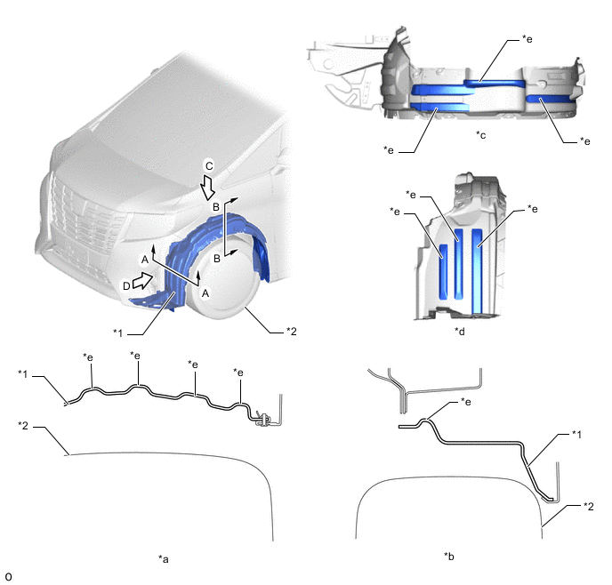
*1 Front Fender Splash Shield Sub-assembly *2 Front Tire *a A - A Cross Section *b B - B Cross Section *c View from C *d View from D *e Groove Structure - - -
Beads are provided on rear wheel house liner to free the high-pressure turbulence outward that causes air resistance in the rear wheel housing by the rotation of the rear tires.
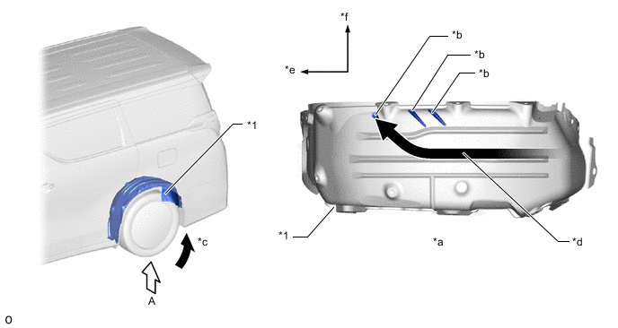
*1 Rear Wheel House Liner - - *a View from A *b Bead *c Airflow Caused by Tire Rotation *d Air Introduction by Bead *e Front Side *f Outside -
The front side fix window assembly uses an aero stabilizing fin to adjust airflow and ensure superior driving stability.
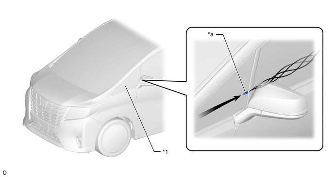
*1 Front Side Fix Window Assembly - - *a Aero Stabilizing Fin - - -
An aero stabilizing fin is provided on the rear combination lamp assembly and a type of aerodynamic technology known as a vortex generator is used for the fin. Small vortexes are purposely generated in airflow to push the vehicle from the left and right sides, thus achieving excellent operation stability.
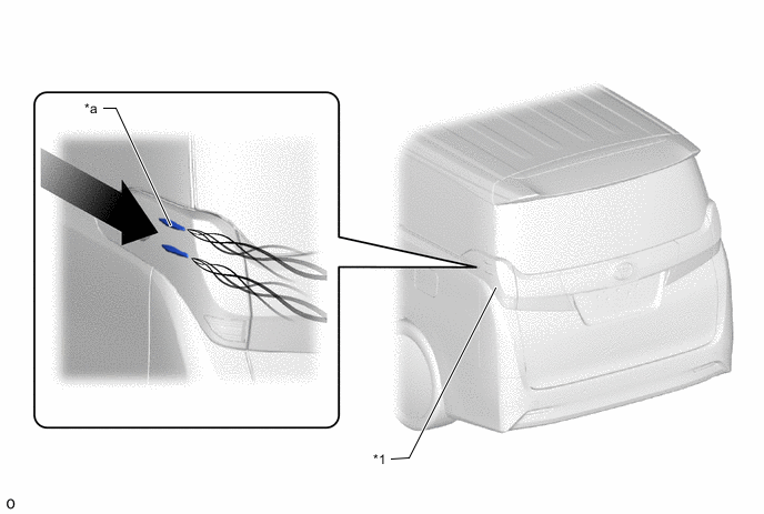
*1 Rear Combination Lamp Assembly - - *a Aero Stabilizing Fin - -
-
-
-