BODY STRUCTURE
-
CONSTRUCTION
-
Impact Absorbing Structure for Frontal Collision
-
A structure that ensures collision energy absorption efficiency, dissipates impact and minimizes cabin deformation during a frontal collision has been achieved.
-
A suspension member stopper (front side member reinforcement No. 2: *6 in illustration) is added to restrain reverse movement of the front suspension crossmember sub-assembly (*5 in illustration), and is given a structure that optimally distributes load to the front side member sub-assembly (*8 in illustration) and front crossmember reinforcement No. 3 while restraining reverse movement of the engine during a frontal collision (*7 in illustration).
-
A rocker inner (steering gear box support member extension: *4 in illustration) using ultra high-tensile strength steel (tensile strength: 980 MPa class) is provided to restrain the amount that the toe board enters the cabin by reducing the amount of reverse movement of the front tires during a frontal collision.
-
A structure is used that distributes impact load transferred from the upper member through the MICS bulkhead* (front body pillar gusset UPR: *3 in illustration) to the front body pillar reinforcement upper (*1 in illustration) and front door inside panel reinforcement (*2 in illustration), which use ultra high-tensile strength steel (tensile strength: 980 MPa class).
Tech Tips
*: MICS: Minimum Intrusion Cabin System
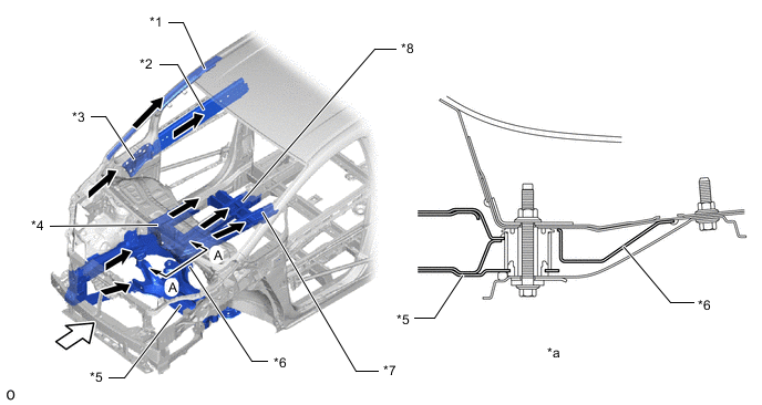
*1 Front Body Pillar Reinforcement Upper *2 Front Door Inside Panel Reinforcement *3 Front Body Pillar Gusset UPR *4 Steering Gear Box Support Member Extension *5 Front Suspension Crossmember Sub-assembly *6 Front Side Member Reinforcement No. 2 *7 Front Crossmember Reinforcement No. 3 *8 Front Side Member Sub-assembly *a A - A Cross Section - - 
Front Impact Energy 
Dissipate -
A dash to frame brace (*4 in illustration) using ultra high-tensile strength steel (tensile strength: 980 MPa class) is provided to the toe board section to restrain the amount that the toe board enters the cabin during a frontal collision.
-
High-tensile strength steel (tensile strength: 590 MPa class) is used in the front side member inner rear (*2 in illustration) and front crossmember reinforcement No. 3 (*1 in illustration), and ultra high-tensile strength steel (tensile strength: 980 MPa class) is used in the front floor side reinforcement (*5 in illustration) and rocker panel reinforcement No. 2 (*3 in illustration), to optimize the structure of the body for frontal collisions.
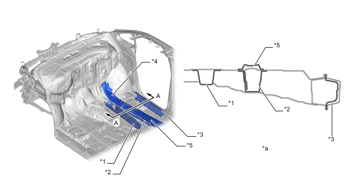
*1 Front Crossmember Reinforcement No. 3 *2 Front Side Member Inner Rear *3 Rocker Panel Reinforcement No. 2 *4 Dash to Frame Brace *5 Front Floor Side Reinforcement - - *a A - A Cross Section - -
-
-
-
Impact Absorbing Structure for Side Collision
-
A structure that ensures collision energy absorption efficiency, dissipates impact and minimizes cabin deformation during a side collision has been achieved.
-
Hot-stamped steel (tensile strength: 1500 MPa class), ultra high-tensile strength steel (tensile strength: 980 MPa class) and high-tensile strength steel (tensile strength: 590/440 MPa class) are used in the body frame, achieving weight reduction while ensuring strength against side collisions.
-
Tailor welded blanks* (tensile strength: 1500 MPa class (*5a in illustration), 590 MPa class (*5b in illustration)) are used in the center body pillar reinforcement outer (*5 in illustration). : Tailor welded blanks are pieces of steel that have been laser welded in advance.
-
*: Tailor welded blanks are pieces of steel that have been laser welded in advance.
-
Ultra high-tensile strength steel (tensile strength: 980 MPa class) is used in the rear floor side member extension RR (*8 in illustration).
-
High-tensile strength steel (tensile strength: 440 MPa class) is used in the floor side member inner (*11 in illustration) and rocker panel reinforcement No. 3 LH (*12 in illustration).
-
High-tensile strength steel (tensile strength: 440: MPa class) is used in the crossmember (front crossmember extension RR (*7 in illustration) and No. 2 front outrigger (*9 in illustration)).
-
The rocker panel reinforcement No. 3 (*10 in illustration) is provided to restrain body deformation when receiving impact during a side collision by transmitting the impact load to the front floor panel reinforcement (*6 in illustration).
-
On models with normal roof, high-tensile strength steel (tensile strength: 440 MPa class) is used in the roof panel reinforcement No. 1 (*1 in illustration) and roof panel reinforcement No. 2 (*2 in illustration) to restrain body deformation during a side collision by transmitting impact load to the opposite side of the vehicle.
-
The door side-impact protect beam sub-assembly (*3 in illustration) and rear door protection beam sub-assembly (*4 in illustration) are optimally positioned to efficiently transmit impact load to every part of the body.
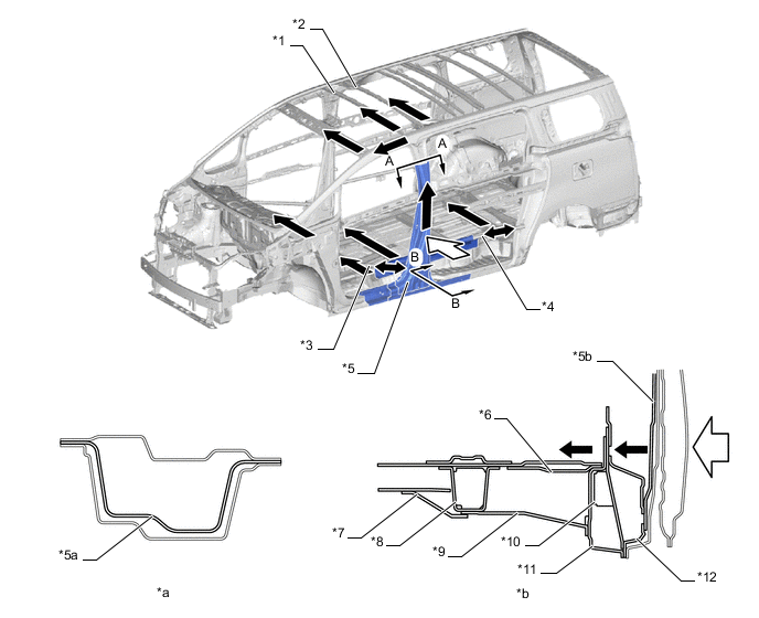
*1 Roof Panel Reinforcement No. 1 *2 Roof Panel Reinforcement No. 2 *3 Door Side-impact Protect Beam Sub-Assembly *4 Rear Door Protection Beam Sub-assembly *5 Center Body Pillar Reinforcement Outer *6 Front Floor Panel Reinforcement *7 Front Crossmember Extension RR *8 Rear Floor Side Member Extension RR *9 No. 2 Front Outrigger *10 Rocker Panel Reinforcement No. 3 *11 Floor Side Member Inner *12 Rocker Panel Reinforcement No. 3 LH Side Impact Energy Dissipate
-
-
-
Impact Absorbing Structure for Rear Collision
-
A structure that ensures collision energy absorption efficiency, dissipates impact and minimizes cabin deformation during a rear collision has been achieved.
-
In order to ensure a survival space during rear collisions, a structure that restrains deformation of the back area of the rear floor side member sub-assembly (*1 in illustration) and efficiently absorbs impact load is used.
-
High-tensile strength steel (tensile strength: 590 MPa class) is used in the rear floor side member (*2 in illustration), and high-tensile strength steel (tensile strength: 440 MPa class) is used in the rear floor side member reinforcement RR No. 3 (*3 in illustration) and rear bumper mounting bracket sub-assembly (*4 in illustration) which are farther to the rear, preventing the rear side member from bending under the initial load. Also, the rear end is axially compressed in order, efficiently absorbing impact load.
-
The seat track assembly (*5 in illustration) is positioned in the center of the vehicle. Impact load is also distributed to the seat track assembly (*5 in illustration), efficiently absorbing energy from the collision and restraining the penetration of objects during a rear collision.
-
Impact load is distributed to the rear suspension member sub-assembly (*6 in illustration), restraining deformation and outward bending of the rear floor side member sub-assembly (*1 in illustration). This also ensures space for passengers during a rear collision.
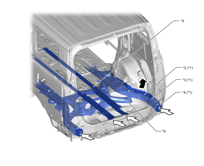
*1 Rear Floor Side Member Sub-assembly *2 Rear Floor Side Member *3 Rear Floor Side Member Reinforcement Rr No. 3 *4 Rear Bumper Mounting Bracket Sub-assembly *5 Seat Track Assembly *6 Rear Suspension Member Sub-assembly Rear Impact Energy Side Member Outward Bending Restraint
-
-
-
Other Occupant Protection Device
-
An energy impact load absorbing structure is used which ensures an impact reducing space for when an occupant's head, etc., impacts the pillar or roof side due to rebound during a collision.
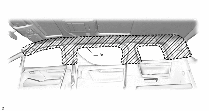
*a Head Impact Protection Structure - -
-
-
Reduction Pedestrian Head Injury
-
The following shape is used for around the front body, thus maintaining necessary rigidity and aiming for a reduction of impact against a pedestrian in a collision with a pedestrian.
-
A hood reinforcement RR (*1 in illustration: VELLFIRE)/hood panel reinforcement (*2 in illustration: ALPHARD) equipped with feet is used at the end of the hood sub-assembly. During a collision with a pedestrian, these feet deform, absorbing impact load and reducing the amount of impact delivered to the pedestrian.
-
A hood reinforcement inner FR (*3 in illustration) is used on the left and right side in the front area of the hood sub-assembly. While ensuring structural rigidity of the hood, the front hood reinforcement inner deforms during a collision with a pedestrian, absorbing impact load and reducing the amount of impact to the pedestrian.
-
Holes are provided on the left and right ends of the hood panel inner (*5 in illustration), cutouts are provided between the mastic seating surfaces (*d in illustration), the hinge bolt has been shortened (*e in illustration) and a vertical frame structure has not been used (*f in illustration) to allow for the effective use of the short hood. These features create a hood sub-assembly that is easily deformable and takes the risk of striking protrusions into consideration. Because of these structures, impact delivered to a pedestrian during a collision is reduced.
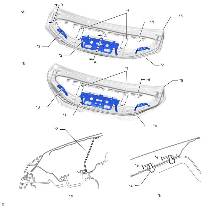
*A ALPHARD *B VELLFIRE *1 Hood Reinforcement RR *2 Hood Panel Reinforcement *3 Hood Reinforcement Inner FR *4 Hinge Bolt *5 Hood Panel Inner - - *a A - A Cross Section *b B - B Cross Section *c Provided Holes *d Provided Cut-outs between Mastic Seating Surfaces *e Shortened Length of Hinge Bolt *f Discontinuation of Vertical Frame Structure -
While ensuring rigidity, the cowl top ventilator louver sub-assembly (*1 in illustration) uses the following structures that easily reduce impact from the upper portion to reduce the amount of impact delivered to the head, etc., of a pedestrian during a collision.
-
The cowl top ventilator louver sub-assembly has reduced thickness (*c in illustration).
-
The cowl top ventilator louver sub-assembly uses a wedge (bent) shape that provides an easily collapsible structure (*d in illustration).
-
The cowl uses open cross sections, providing a structure that easily reduces impact (*e in illustration).
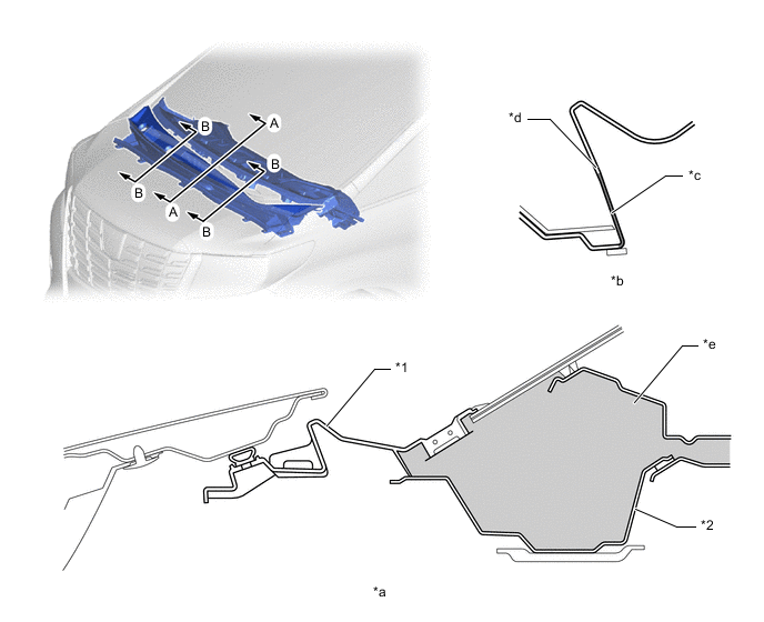
*1 Cowl Top Ventilator Louver Sub-assembly *2 Cowl Top Panel Sub-assembly Outer *a A - A Cross Section *b B - B Cross Section *c Thinner Portion *d Wedge (Bent) Shape *e Open Cross Section - -
-
-
-