POWER SLIDE DOOR SYSTEM
-
CONSTRUCTION
-
The slide door handle assembly consists mainly of various control levers, various switches and an inside handle.
-
When the slide door is fully opened or fully closed, the control lever in the slide door handle assembly is operated to disengage the latch in the slide door front lock assembly and the rear slide door lock assembly in the slide door via the cable.
-
The status of each control lever is detected via an inside handle switch (open), inside handle switch (close) and outside handle switch.
Figure 1. Slide Door Handle Assembly LH
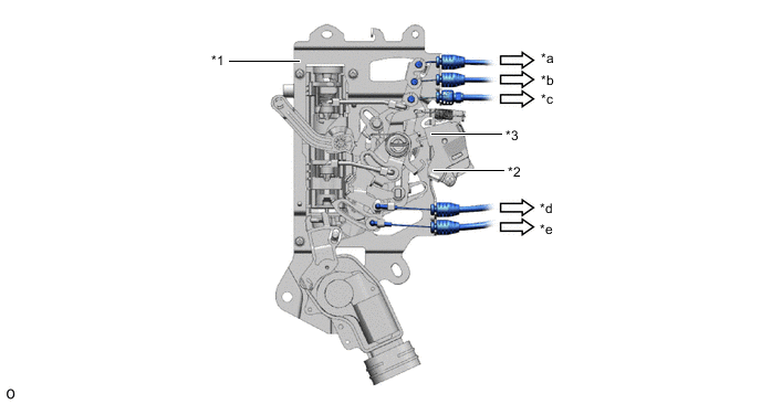
*1 Slide Door Handle Assembly *2 Outside Handle Switch *3 Inside Handle Switch (Open/Close) - - *a To Slide Door Front Lock Assembly *b To Rear Slide Door Lock Assembly *c To Slide Door Full Open Stop Lock Assembly *d To Slide Door Front Lock Assembly *e To Rear Slide Door Lock Assembly - - Figure 2. Inside Handle Switch
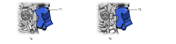
*1 Inside Handle Switch (Open) On *2 Inside Handle Switch (Close) On *a Inside Handle Open Operation *b Inside Handle Close Operation Figure 3. Outside Handle Switch

*1 Outside Handle Switch ON - - Slide Door Handle Operation and Switch Condition Handle Operation Inside Handle Switch Outside Handle Switch Open Close Not Operation Off Off Off Inside Handle Open Operation On Off Off Inside Handle Close Operation Off On Off Outside Handle Operation Off Off On
-
-
OPERATION
-
Open Operation (Slide Door Front Lock Assembly and Rear Slide Door Lock Assembly Locks Released) by Operation of Slide Door Inside Handle
-
The No. 1 rod connected to the slide door inside handle moves in the direction indicated by the arrow in the illustration (*a) according to the operation of the slide door inside handle.
-
This rotates the No. 3 control lever in the direction indicated by the arrow in the illustration (*b) and turns the inside handle switch (open) on.
-
At the same time, the rotation of the No. 2 control lever as indicated by the arrow in the illustration (*c) pulls the front slide door lock cable and slide door lock cable, and releases the locks of the slide door front lock assembly and rear slide door lock assembly.
Figure 4. Slide Door Handle Assembly LH
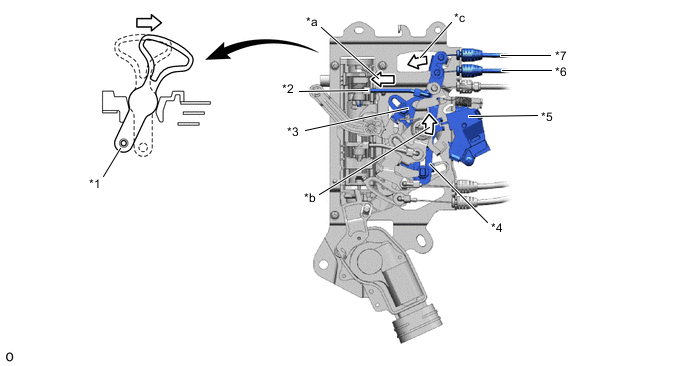
*1 Inside Handle *2 No. 1 Rod *3 No. 3 Control Lever *4 No. 2 Control Lever *5 Inside Handle Switch (Open) *6 Slide Door Lock Cable *7 Front Slide Door Lock Cable - - *a No. 1 Rod Operation Direction *b No. 3 Control Lever Rotation Direction *c No. 2 Control Lever Rotation Direction - -
-
-
Close Operation (Slide Door Full Open Stop Lock Assembly Lock Released) by Operation of Slide Door Inside Handle
-
The No. 2 rod connected to the slide door inside handle moves in the direction indicated by the arrow in the illustration (*a) according to the operation of the slide door inside handle.
-
This rotates the No. 3 control lever in the direction indicated by the arrow in the illustration (*b) and turns the inside handle switch (close) on.
-
At the same time, the rotation of the No. 6 control lever as indicated by the arrow in the illustration (*c) pulls the slide door full open stop lock cable, and releases the lock of the slide door full open stop lock assembly.
Figure 5. Slide Door Handle Assembly LH
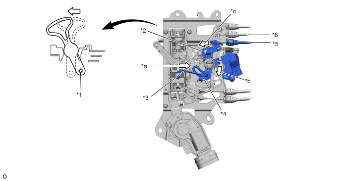
*1 Inside Handle *2 No. 3 Control Lever *3 No. 2 Rod *4 No. 6 Control Lever *5 Inside Handle Switch (Close) *6 Slide Door Full Open Stop Lock Cable *a No. 2 Rod Operation Direction *b No. 3 Control Lever Rotation Direction *c No. 6 Control Lever Rotation Direction - -
-
-
Slide Door Outside Handle Operation (Slide Door Front Lock Assembly, Rear Slide Door Lock Assembly and Slide Door Full Open Stop Lock Assembly Locks Released)
-
The rear door lock open rod connected to the slide door front lock assembly moves in the direction indicated by the arrow in the illustration (*a) according to the operation of the slide door outside handle.
-
This rotates the bell crank of the slide door front lock assembly in the direction indicated by the arrow in the illustration (*b) and pulls the outside handle cable in the direction of the arrow shown in the illustration (*c).
-
The outside handle cable is pulled, and the No. 5 control lever rotates in the direction indicated by the arrow in the illustration (*d) and turns the outside handle switch on.
-
At the same time, the rotation of the No. 6 control lever and No. 2 control lever as indicated by the arrow in the illustration (*e) pulls the front slide door lock cable, slide door lock cable and slide door full open stop lock cable, and releases the locks of the slide door front lock assembly, rear slide door lock assembly and slide door full open stop lock assembly.
Figure 6. Slide Door Handle Assembly LH
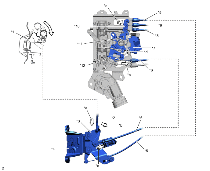
*1 Slide Door Outside Handle *2 Rear Door Lock Open Rod *3 Bell Crank *4 Slide Door Front Lock Assembly *5 Front Slide Door Lock Cable *6 Outside Handle Cable *7 Outside Handle Switch *8 Slide Door Full Open Stop Lock Cable *9 Slide Door Lock Cable *10 No. 2 Control Lever *11 No. 6 Control Lever *12 No. 5 Control Lever *a Rear Door Lock Open Rod Operation Direction *b Control Lever Rotation Direction *c Outside Handle Cable Operation Direction *d No. 5 Control Lever Rotation Direction *e No. 6 Control Lever and No. 2 Control Lever Rotation Direction - -
-
-