SLIDING ROOF SYSTEM
-
FUNCTION OF MAIN COMPONENTS
Component Function Sliding Roof Drive Gear Assembly Sliding Roof Motor Controlled by the sliding roof ECU and slides the sliding roof glass. Sliding Roof ECU Controls the sliding roof motor based on the built-in pulse sensor (Hall IC) and various input signals. Sliding Roof Switch Sends operation signals to the sliding roof ECU. Multiplex Network Master Switch Assembly Window Lock Switch Prohibits the opening and closing operation of the sliding roof. Door Courtesy Light Switch Assembly (Driver Side) Detects the opening and closing condition of the door and sends the data to the main body ECU (multiplex network body ECU). Main Body ECU (Multiplex Network Body ECU) Judges that the sliding roof open warning is required based on the data about the sliding roof position from the sliding roof ECU and sends a warning request to the combination meter assembly. Combination Meter Assembly
-
Receives a warning request from the main body ECU (multiplex network body ECU) and sounds the built-in buzzer.
-
Receives a warning request from the main body ECU (multiplex network body ECU) and displays a message.
-
-
SYSTEM CONTROL
-
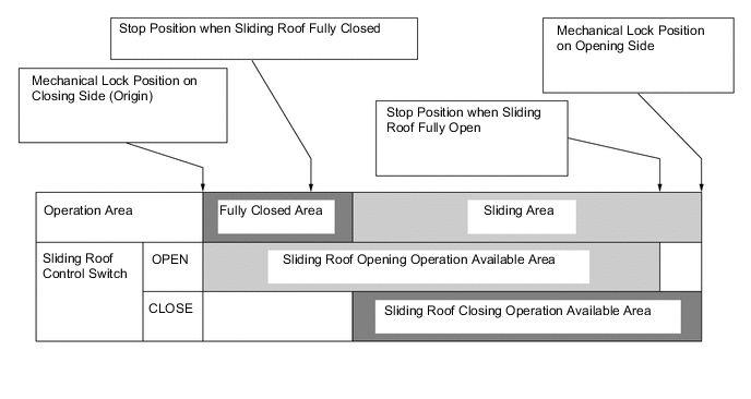
The sliding roof ECU detects the sliding roof glass position according to signals from the pulse sensor (Hall IC) as shown in the illustration below by regarding the mechanical lock position on the closing side of the sliding roof as the origin. The sliding roof ECU controls the sliding roof motor based on the position data and operation signals from the sliding roof control switch.
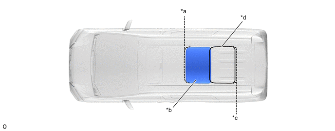
*a Mechanical Lock Position on Closing Side (Origin) *b Stop Position when Sliding Roof Fully Closed *c Mechanical Lock Position on Opening Side *d Stop Position when Sliding Roof Fully Open Figure 1. Sliding Roof Position Data
Tech Tips
The sliding roof ECU memorizes the initial position of the sliding roof. This memory is not cleared even if the battery terminals are disconnected. However, initialization is necessary after the sliding roof drive gear assembly is replaced. For details, refer to the Repair Manual.
-
-
FUNCTION
-
The sliding roof system has the following functions:
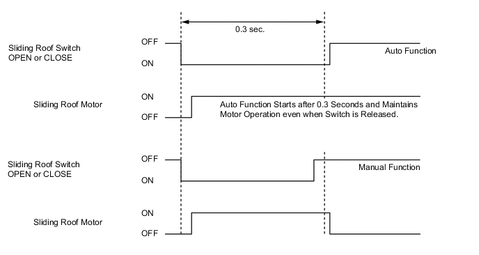
Function Outline Manual Open-and-close Opens and closes the sliding roof when the sliding roof switch is pressed for less than 0.3 seconds. The sliding roof stops as soon as the switch is released. One-touch Auto Open-and-close
-
Fully opens the sliding roof when the sliding roof switch (OPEN) is pressed for 0.3 seconds or more.
-
Fully closes the sliding roof when the sliding roof switch (CLOSE) is pressed for 0.3 seconds or more.
Auto Stop Automatically stops the opening operation of the sliding roof when a certain amount of load is applied to the sliding roof glass during the opening operation. Jam Protection Automatically stops the closing operation of the sliding roof when a certain amount of load is applied to the sliding roof glass during the closing operation, and performs a reverse operation. Window Lock Stops and prohibits sliding roof operation by operating the window lock switch in the multiplex network master switch assembly. Sliding Roof Open Warning Sounds the buzzer in the combination meter assembly and displays a message on the combination meter assembly to warn the driver when the engine switch is turned from on (IG) to off and the driver door is opened with the sliding roof open. -
-
Manual Open-and-close Function
-
With the position information already set, while the engine switch is on (IG) and the sliding roof switch (OPEN or CLOSE) is being operated, this function performs the opening and closing operation of the sliding roof.
-
When any of the following conditions are met, manual operation will be stopped:
Operation Stop Condition Manual Open
-
The sliding roof switch (OPEN) is turned off.
-
A malfunction is detected in the sliding roof switch.
-
The stop position when the sliding roof is fully open is detected.
-
The motor locked condition*1 is detected.
-
The window lock switch in the multiplex network master switch assembly is turned on.
-
The continuous current to the sliding roof motor has been maintained for 20 seconds or more.
-
A malfunction is detected in the pulse sensor (Hall IC).
-
A sliding roof position malfunction is detected.
Manual Close
-
The sliding roof switch (CLOSE) is turned off.
-
A malfunction is detected in the sliding roof switch.
-
The stop position when the sliding roof is fully closed is detected.
-
Normal load*2 or motor locked condition*1 is detected.
-
The window lock switch in the multiplex network master switch assembly is turned on.
-
The continuous current to the sliding roof motor has been maintained for 20 seconds or more.
-
A malfunction is detected in the pulse sensor (Hall IC).
-
A sliding roof position malfunction is detected.
Tech Tips
*1: No edge changes occur in the output signals from the pulse sensor (Hall IC).
*2: The fluctuation in the motor rotation speed exceeds the threshold.
-
-
-
One-touch Auto Open-and-close Function
-
When the sliding roof switch (OPEN or CLOSE) has been pressed for 0.3 seconds or more with the engine switch on (IG), the auto function activates to move the sliding roof up to the fully open or closed position without having to press and hold the switch.
-
When any of the following conditions are met, auto operation will be stopped:
Operation Stop Condition Auto Open
-
The sliding roof switch (OPEN) is operated again.
-
The sliding roof switch (CLOSE) is turned on.
-
A malfunction is detected in the sliding roof switch.
-
The stop position when the sliding roof is fully open is detected.
-
The motor locked condition* is detected.
-
The window lock switch in the multiplex network master switch assembly is turned on.
-
The continuous current to the sliding roof motor has been maintained for 20 seconds or more.
-
A malfunction is detected in the pulse sensor (Hall IC).
-
A malfunction detection about the sliding roof position is detected.
Auto Close
-
The sliding roof switch (CLOSE) is operated again.
-
The sliding roof switch (OPEN) is turned on.
-
A malfunction is detected in the sliding roof switch.
-
The stop position when the sliding roof is fully closed is detected.
-
Overload or motor locked condition*1 is detected.
-
The window lock switch in the multiplex network master switch assembly is turned on.
-
The continuous current to the sliding roof motor has been maintained for 20 seconds or more.
-
A malfunction is detected in the pulse sensor (Hall IC).
-
A malfunction detection about the sliding roof position is detected.
Tech Tips
*: No edge changes occur in the output signals from the pulse sensor (Hall IC).
-
-
-
Jam Protection
-
When an overload* is detected while the sliding roof is being closed, this function stops the sliding roof operation and operates in reverse (opening operation) approximately 200 mm or up to the fully opening position.
Tech Tips
*: This means that there are no edges in the output signals from the pulse sensor (Hall IC) or fluctuations in the motor rotation speed exceed the threshold.
-
-
-
FAIL-SAFE
-
If a difference between the present sliding roof glass position and the position data stored in the sliding roof ECU is more than the predetermined level, a malfunction is detected in the pulse sensor (Hall IC) or a malfunction occurs in the jam protection function, the sliding roof ECU will be switched to the control mode for when the system cannot learn the position data.
Fail-safe List Function Outline Position Data Malfunction Judgment This function determines position detection malfunctions during operation, and considers the initialization of the sliding roof glass to be incomplete. Continuous Operation Limit This function restricts the continuous operation time of the motor. Forced Learned Operation This function is utilized to make the position data indefinite and considers initialization incomplete as an avoidance method for when the sliding roof cannot be fully closed. Pulse Sensor (Hall IC) Malfunction Judgment This function judges a malfunction in the pulse sensor (Hall IC) and carries out the fail-safe operation according to the malfunction. Communication Disconnection Management This function stores data for a certain period of time during communication disconnection, and then sets the position data to the default.
-
-
DIAGNOSIS
-
If there is a malfunction in the system, the sliding roof ECU stores the Diagnostic Trouble Codes (DTCs) in its memory. For details, refer to the Repair Manual.
-