POWER WINDOW CONTROL SYSTEM
-
FUNCTION OF MAIN COMPONENTS
Component Function Power Window Regulator Motor Assembly Power Window ECU Controls the power window motor activation according to signals from various switches, the main body ECU (multiplex network body ECU) and the built-in pulse sensor (Hall IC). Power Window Motor Controlled by the power window ECU and drives the power window regulator to move the door glass up and down. Multiplex Network Master Switch Assembly Window Lock Switch Sends operation signals to the power window ECU in each door. Power Window Regulator Switch (Driver Door) Sends operation signals to the power window ECU in the driver door. Remote Switch (Front Passenger Door) Sends operation signals to the power window ECU in the front passenger door. Remote Switch (Slide Door RH) Sends operation signals to the power window ECU in the slide door RH. Remote Switch (Slide Door LH) Sends operation signals to the power window ECU in the slide door LH. Power Window Regulator Switch Assembly Front Passenger Door Sends operation signals to the power window ECU in the front passenger door. Slide Door RH Sends operation signals to the power window ECU in the slide door RH. Slide Door LH Sends operation signals to the power window ECU in the slide door LH. Door Courtesy Light Switch Assembly Driver Side Detects the opening and closing condition of the door and sends the data to the main body ECU (multiplex network body ECU). Front Passenger Side Front Door Lock Assembly RH Sends data about the operation condition of the door lock control switch to the main body ECU (multiplex network body ECU). Main Body ECU (Multiplex Network Body ECU)
-
Sends power window operation permission signals to the power window ECU in each door.
-
Sends power window control signals to the power window ECU in each door.
Certification ECU (Smart Key ECU Assembly) Receives electrical key transmitter sub-assembly operation signals from the door control receiver and sends them to the main body ECU (multiplex network body ECU). -
-
SYSTEM CONTROL
-
The power window control system has the following functions:
Function Outline Manual Up-and-down The manual up-and-down function causes the window to open or close while the multiplex network master switch assembly or power window regulator switch assembly is being pulled halfway up or pushed halfway down. The window stops as soon as the switch is released. One-touch Auto Up-and-down The one-touch auto up-and-down function enables the window to be fully opened or closed by firmly operating the multiplex network master switch assembly or power window regulator switch assembly. Remote Control The remote switches in the multiplex network master switch assembly can control the up-and-down operation of the windows. Variable Speed Control This control minimizes the occurrence of noise during the power window open/close operation by changing the operating speed of the power window regulator motor. Jam Protection The jam protection function automatically stops the power window and moves it downward if a foreign object gets jammed in the window during an up operation. Catch Protection The catch protection function automatically stops the power window if a foreign object gets caught in the window during a down operation. Key Off Operation
-
This function makes it possible to operate the power windows for approximately 43 seconds after the engine switch is turned off, if either front door is not opened.
-
If the window lock switch is off, the windows can be operated using any of the power window regulator switch assemblies. If the window lock switch is on, only the multiplex network master switch assembly can be used to operate the windows.
Key-linked Up-and-down
-
When the transmitter is not in the interior detection area, the driver door is locked, and the mechanical key in the driver door is turned and maintained in the lock direction for 1.5 seconds or more, the main body ECU (multiplex network body ECU) activates the power window motors to raise all door windows while the mechanical key is turned.
-
Similarly, when the driver door is unlocked, turning and maintaining the driver door key cylinder in the unlock direction for 1.5 seconds or more will cause all door windows to be lowered.
Transmitter-linked Up-and-down
-
When the certification ECU (smart key ECU assembly) receives an unlock signal from the transmitter for longer than 3 seconds, the main body ECU (multiplex network body ECU) controls the power window motors in accordance with the signal to open the windows.
-
Similarly, when the certification ECU (smart key ECU assembly) receives a lock signal from the transmitter for longer than 3 seconds, the main body ECU (multiplex network body ECU) controls the power window motors in accordance with the signal to close the windows.
Soft Stop During an up operation of the power window, the power window ECU stops the current to the power window motor right before the door glass is fully closed. Window Lock
-
Operation of the front passenger door window and either slide door window at each power window regulator switch assembly is disabled when the window lock switch is pressed.
-
Even when the window lock switch is pressed, the front passenger door window and either slide door window can be operated using the multiplex network master switch assembly.
Window Open Warning When the engine switch is turned from on (IG) to off and the driver door is opened with the power window glass open, the multi buzzer in the combination meter assembly sounds once. Then, a warning message appears on the accessory meter assembly and the master warning light blinks. Customization The on or off setting of some functions can be performed using the Global TechStream (GTS). For details, refer to the Repair Manual. Tech Tips
The ECU built into each power window motor stores the initial position of its door window. The initial position is not cleared even if the terminals, fuses or the power window motor connector are disconnected. However, after removing or reinstalling window components, or replacing the power window regulator switch assembly or power window regulator motor assembly, the stored initial position data must be cleared and/or initialization must be performed. For details, refer to the Repair Manual.
-
-
Variable Speed Control
-
Opening Power Window
-
The power window regulator motor assembly increases the door window opening speed to normal speed when the front door window glass is between the fully closed position and open position of a specified value. Also, the assembly reduces the opening speed from normal speed when the door window glass is between the fully opened position and an open position of a specified value.
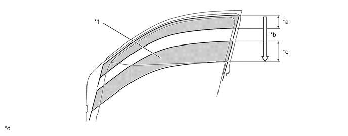
*1 Door Glass - - *a Acceleration *b Normal Speed *c Deceleration *d The operation has been expressed in the illustration.
-
-
Closing Power Window
-
The power window regulator motor assembly increases the door window glass closing speed to normal speed when the door window glass is between the fully opened position and an open position of a specified value. Also, the assembly reduces the closing speed from normal speed when the door window glass is between the fully closed position and a close position of a specified value.
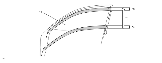
*1 Door Glass - - *a Deceleration *b Normal Speed *c Acceleration *d The operation has been expressed in the illustration.
-
-
-
Jam Protection Function
-
A jam protection function automatically stops the power window and moves it downward if a foreign object gets jammed in the door window during up an operation.
-
The operation of the jam protection function is described below:
Operation Function Front Door Rear Door Auto up operation (except remote operation) Down operation of 137 mm (5.4 in.) or 5 seconds Down operation of 155 mm (6.1 in.) or 5 seconds Manual up operation Down operation of 25 mm (1.0 in.) or 5 seconds Down operation of 30 mm (1.2 in.) or 5 seconds -
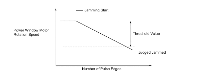
The power window ECU determines if a foreign object gets jammed according to changes in the output signal from the pulse sensor (Hall IC). Both of the following 2 judgment methods are used:
Figure 1. Judgment Method (Overload Detection)
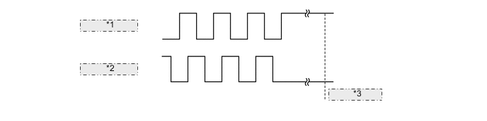
*1 Pulse Signal 1 *2 Pulse Signal 2 *3 Judged Jammed Figure 2. Judgment Method (Rotation Speed Comparison)
-
-
Catch Protection Function
-
The catch protection function automatically stops the power window if a foreign object gets caught in the window during a down operation.
-
The power window ECU determines if a foreign object gets caught according to changes in the output signal from the pulse sensor (Hall IC). The judgment method is as follows:
Figure 3. Judgment Method (Rotation Speed Comparison)

-
-
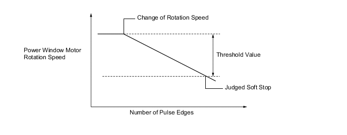
Soft Stop Function
-
During an up operation of the power window, the soft stop function stops the current to the power window motor right before the door glass is fully closed. This reduces the load on the door glass outer weatherstrip.
-
The power window ECU determines if the door glass stop position is detected according to changes in the output signal from the pulse sensor (Hall IC). The judgment method is as follows:
Figure 4. Judgment Method (Rotation Speed Comparison)
-
-
-
FAIL-SAFE
-
If a pulse sensor (Hall IC) in the power window regulator motor assembly malfunctions, the power window control system enters fail-safe mode. For details, refer to the Repair Manual.
-
-
DIAGNOSIS
-
When the power window ECU detects a malfunction in the power window control system, a Diagnostic Trouble Code (DTC) is stored in memory.
-
The DTC can be read using the Global TechStream (GTS). For details, refer to the Repair Manual.
-