AIR CONDITIONING SYSTEM
-
CONSTRUCTION
-
The 7SES17C type compressor with pulley assembly is used on models with a 2AR-FE engine.
-
The 7SAS17C type compressor with pulley assembly is used on models with a 2GR-FE engine.
-
These compressor with pulley assemblies are continuously variable capacity type air conditioning compressors. Their capacities can be varied in accordance with the cooling load of the air conditioning system.
-
The 7SES17C type compressor with pulley assembly consists of a Damper Limiter (DL) type pulley, shaft, lug plate, swash plate, piston, shoe, crank chamber, cylinder and solenoid control valve.
-
The 7SAS17C type compressor with pulley assembly consists of a magnet clutch assembly, shaft, lug plate, swash plate, piston, shoe, crank chamber, cylinder and solenoid control valve.
-
A shaft oil separator which separates compressor oil and refrigerant is provided.
-
A solenoid control valve that adjusts the flow of a refrigerant so that the compressor with pulley assembly capacity can be controlled as desired is provided.
Figure 1. 7SES17C Type Compressor with Pulley Assembly (Models with 2AR-FE Engine)
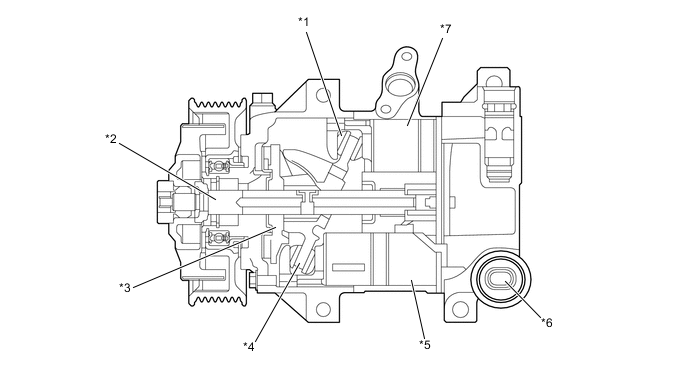
*1 Shoe *2 Shaft *3 Lug Plate *4 Swash Plate *5 Cylinder *6 Solenoid Control Valve *7 Piston - - Figure 2. 7SAS17C Type Compressor with Pulley Assembly (Models with 2GR-FE Engine)
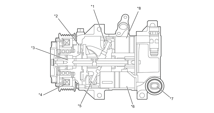
*1 Shoe *2 Lug Plate *3 Shaft *4 Magnet Clutch Assembly *5 Swash Plate *6 Cylinder *7 Solenoid Control Valve *8 Piston
-
Shaft Oil Separator
-
Compressor oil, which has been mixed with the refrigerant and circulated in the air conditioning cycle, is separated by the shaft oil separator built into the shaft and accumulated in the compressor.
-
For the shaft oil separator, an oil return passage is located between the swash plate with less oil and the lug plate, and refrigerant gas in which small amount of oil is mixed is sent to the intake chamber. As a result, the oil circulation amount in the air conditioning cycle is reduced.
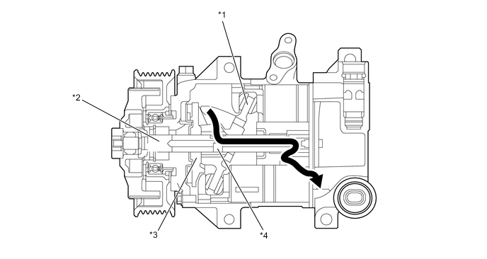
*1 Swash Plate *2 Shaft *3 Lug Plate *4 Shaft Oil Separator 
Refrigerant Gas - -
-
-
Damper Limiter (DL) Type Pulley (7SES17C Type Compressor with Pulley Assembly)
-
This pulley contains a damper to absorb the torque fluctuations of the engine and a limiter mechanism to protect the drive belt in case the compressor locks. In the event that the compressor locks, the limiter mechanism causes the spoke portion of the pulley to break, thus separating the pulley from the compressor with pulley assembly.
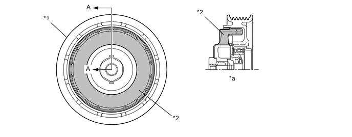
*1 Damper Limiter (DL) Type Pulley *2 Damper *a A - A Cross Section - -
-
-
-
-
OPERATION
-
Variable Capacity Operation
-
The crank chamber is connected to the suction passage. A solenoid control valve is provided between the suction passage (low pressure) and the discharge passage (high pressure).
-
The solenoid control valve operates under duty cycle control in accordance with the signals from the air conditioning amplifier assembly.
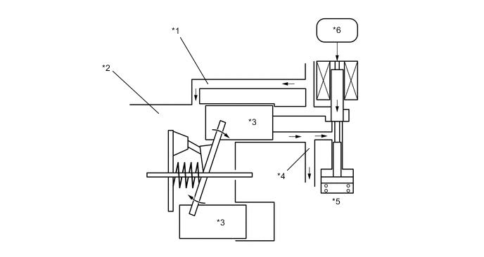
*1 Suction Passage *2 Crank Chamber *3 Piston *4 Discharge Passage *5 Solenoid Control Valve *6 Air Conditioning Amplifier Assembly -
When the solenoid control valve closes (the solenoid coil is energized), a difference in pressure is created and the pressure in the crank chamber decreases. Then, the pressure applied to the right side of the piston becomes greater than the pressure applied to the left side of the piston. This compresses the spring and tilts the lug plate. As a result, the piston stroke increases and the discharge capacity increases.
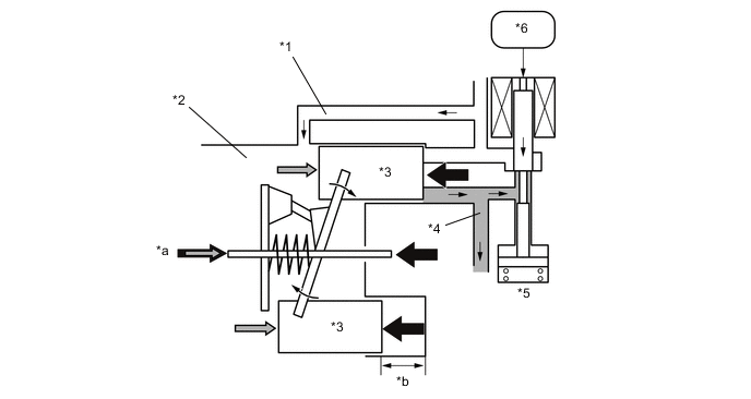
*1 Suction Passage *2 Crank Chamber *3 Piston *4 Discharge Passage *5 Solenoid Control Valve *6 Air Conditioning Amplifier Assembly *a Crank Chamber Pressure + Spring Force *b Piston Stroke: Large -
When the solenoid control valve opens (the solenoid coil is not energized), the difference in pressure disappears. Then, the pressure applied to the left side of the piston becomes the same as the pressure applied to the right side of the piston. Thus, the spring elongates and eliminates the tilt of the lag plate. As a result, there is a small piston stroke and the discharge capacity decreases.
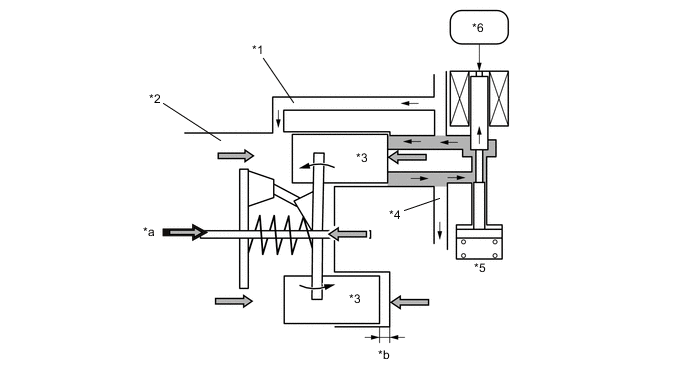
*1 Suction Passage *2 Crank Chamber *3 Piston *4 Discharge Passage *5 Solenoid Control Valve *6 Air Conditioning Amplifier Assembly *a Crank Chamber Pressure + Spring Force *b Piston Stroke: Small
-
-
Variable Crank Suction (CS) Valve
-
The refrigerant in the crank chamber, which varies the capacity of the compressor, returns to the intake chamber through a valve and is compressed by the compressor. The variable CS valve is located between the crank chamber and the intake chamber. The opening amount of the variable CS valve is reduced when the capacity is being varied to set the amount of refrigerant in the crank chamber to only the very minimum amount necessary for control, thus reducing the power required to drive the compressor.
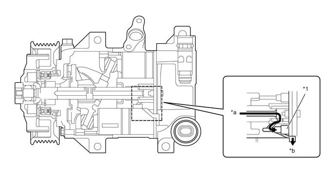
*1 Variable CS Valve - - *a From Crank Chamber *b To Intake Chamber Refrigerant Flow - -
-
-
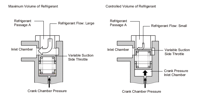
Variable Suction Side Throttle Operation
-
Refrigerant inlet pressure is applied to the top of the variable suction side throttle, and crank chamber pressure is applied to the bottom of the variable suction side throttle.
-
The pressure difference moves the variable suction side throttle up and down, expanding and contracting the refrigerant inlet passage.
-
When the refrigerant flow is at its maximum, the refrigerant inlet pressure is greater than the crank chamber pressure. This causes the variable suction side throttle to move down, fully opening the refrigerant inlet passage and lowering the refrigerant inlet resistance.
-
When the amount of refrigerant flow is controlled, the crank chamber pressure is greater than the refrigerant inlet pressure, raising the variable inlet throttle to contract the flow passage.
-
These controls suppress noise by reducing pulsation from the refrigerant inlet.
-
-