AIR CONDITIONING SYSTEM
-
CONSTRUCTION
-
A front air conditioning unit that is compatible with left and right independent temperature control is used.
-
An inside-and-outside dual air layer type air conditioning unit is used on LHD models. This type of air conditioning unit introduces outside air to the upper side and circulates inside air to the lower side, thus achieving anti-fogging performance and ventilation loss reduction.
-
A Beneficial Refrigerant Stream (BRS) type evaporator is used on models with a 2GR-FE engine.
-
A cold storage evaporator is used on models with a 2AR-FE engine. The cold storage evaporator with built-in cold insulator uses the cold energy accumulated in the cold insulator to blow cool air inside the vehicle when the engine is stopped according to the stop and start system. As a result, engine restarts according to requests from air conditioning control have been suppressed.
Tech Tips
If the cold insulator is not cooled, air blown by the system cannot be cooled.
-
A Straight Flow Aluminum-II (SFA-II) heater core that is compact and offers advanced performance is used.
-
A compact wide-angle high flow defroster that gives the defroster nozzle assembly inner wall a radial shape is used to ensure superior defroster performance.
Figure 1. Air Conditioning Unit Layout Parts Location (LHD Models)
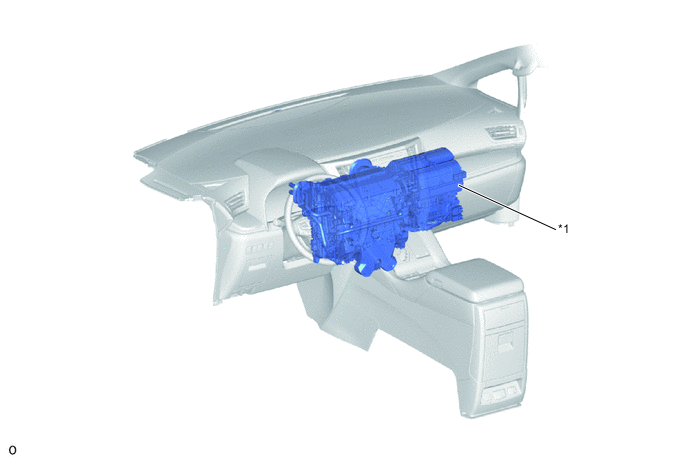
*1 Front Air Conditioning Unit - - Figure 2. Air Conditioning Unit Layout Parts Location (RHD Models)
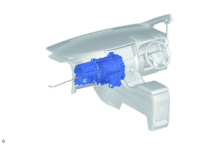
*1 Front Air Conditioning Unit - - Figure 3. Duct Layout Parts Location (LHD Models)
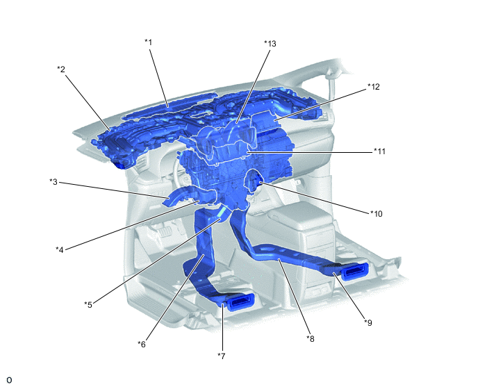
*1 Center Defroster Nozzle Assembly *2 Instrument Panel Sub-assembly
-
Driver Side Side Register Duct
-
Driver Side Side Defroster Duct
-
Front Passenger Side Side Register Duct
-
Front Passenger Side Side Defroster Duct
*3 Driver Side Footwell Register Duct (No. 3 Air Duct Sub-assembly RH) *4 Driver Side Footwell Register Duct (No. 2 Air Duct Sub-assembly RH) *5 Driver Side Rear Footwell Register Duct (Rear No. 1 Air Duct RH) *6 Driver Side Rear Footwell Register Duct (Rear No. 2 Air Duct RH) *7 Driver Side Rear Footwell Register Duct (Rear No. 3 Air Duct RH) *8 Front Passenger Side Rear Footwell Register Duct (Rear No. 1 Air Duct LH) *9 Front Passenger Side Rear Footwell Register Duct (Rear No. 2 Air Duct LH) *10 Front Passenger Side Footwell Register Duct (No. 2 Air Duct Sub-assembly LH) *11 Defroster Nozzle Assembly *12 Fresh Air Inlet Duct (No. 1 Air Duct Sub-assembly) *13 Center Register Duct (No. 1 Heater to Register Duct) - - Figure 4. Duct Layout Parts Location (RHD Models)
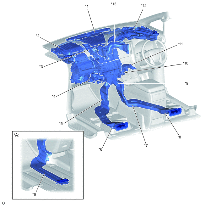
*A Models with Front Passenger Super Long Slide Seat - - *1 Center Defroster Nozzle Assembly *2 Fresh Air Inlet Duct (No. 1 Air Duct Sub-assembly) *3 Defroster Nozzle Assembly *4 Front Passenger Side Footwell Register Duct (No. 2 Air Duct Sub-assembly LH) *5 Front Passenger Side Rear Footwell Register Duct (Rear No. 1 Air Duct LH) *6 Front Passenger Side Rear Footwell Register Duct (Rear No. 2 Air Duct LH) *7 Driver Side Rear Footwell Register Duct (Rear No. 2 Air Duct RH) *8 Driver Side Rear Footwell Register Duct (Rear No. 3 Air Duct RH) *9 Driver Side Rear Footwell Register Duct (Rear No. 1 Air Duct RH) *10 Driver Side Footwell Register Duct (No. 2 Air Duct Sub-assembly RH) *11 Driver Side Footwell Register Duct (No. 3 Air Duct Sub-assembly RH) *12 Instrument Panel Sub-assembly
-
Driver Side Side Register Duct
-
Driver Side Side Defroster Duct
-
Front Passenger Side Side Register Duct
-
Front Passenger Side Side Defroster Duct
*13 Center Register Duct (No. 1 Heater to Register Duct) - - -
-
-
OPERATION
-
Mode Position and Damper Operation
Figure 5. LHD Models
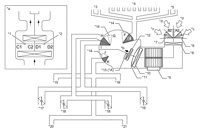
*A Models for China and Russia - - *1 Driver Side Air Mix Control Damper *2 Front Passenger Side Air Mix Control Damper *3 Driver Side Side Defroster *4 Front Defroster *5 Passenger Side Side Defroster *6 Air Inlet Control Damper (Lower Side) *7 Air Inlet Control Damper (Upper Side) *8 Clean Air Filter *9 Blower Motor with Fan Sub-assembly *10 No. 1 Cooler Evaporator Sub-assembly *11 Air Mix Control Damper *12 Heater Radiator Unit Sub-assembly *13 PTC Heater (Quick Heater Assembly) *14 Mode Switching Damper *15 Driver Side Footwell Register *16 Passenger Side Footwell Register *17 Driver Side Side Register *18 Center Register *19 Passenger Side Side Register *20 Driver Side Rear Footwell Register *21 Passenger Side Rear Footwell Register - - *a Illustration Image View from [A] *b [A] View *c Recirculated Air *d Fresh Air Tech Tips
This illustration is a model diagram showing the damper positions in each mode. The parts layout and the number of the dampers in the illustration are different from those of the actual system.
Mode Position and Damper Operation (LHD Models) Damper Control Position Damper Position Operation Air Inlet Control Damper FRESH A1, B1 Brings in fresh air. RECIRCULATION A2, B2 Recirculates internal air. Air Mix Control Damper Max COOL to Max HOT Temperature Setting C1 to C2 Varies the driver side mixture ratio of warm air and cool air in order to continuously regulate the temperature between max hot and max cool. D1 to D2 Varies the front passenger side mixture ratio of warm air and cool air in order to continuously regulate the temperature between max hot and max cool. Mode Control Damper FACE E, G, K Air blows out of the center registers and side registers. BI-LEVEL E, G to I, J to K Air blows out of the center registers, side registers, footwell registers and rear footwell registers. FOOT E, (E to F)*, H, J Air blows out of the footwell registers and rear footwell registers. In addition, air blows out slightly from the side registers, front defroster* and side defrosters*. FOOT/DEF F, H, J to K Air blows out of the front defroster, side defrosters, footwell registers and rear footwell registers. A small amount of air also blows out from the side registers. DEF F, H, K Air blows out of the front defroster and side defrosters. A small amount of air also blows out from the side registers. Tech Tips
*: During system control in AUTO mode
Figure 6. RHD Models
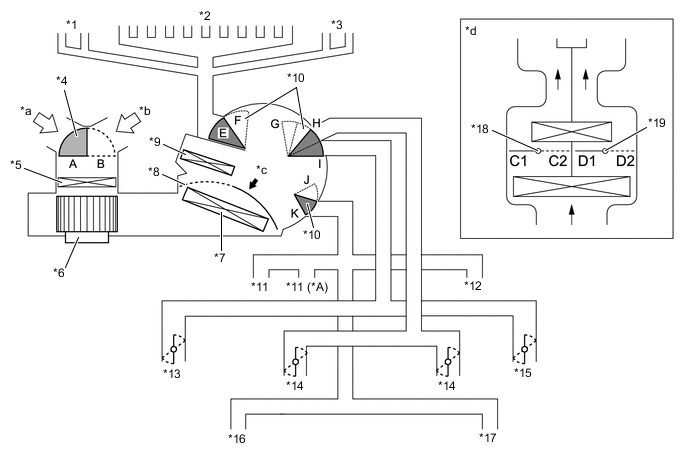
*A Models with Front Passenger Super Long Slide Seat - - *1 Passenger Side Side Defroster *2 Front Defroster *3 Driver Side Side Defroster *4 Air Inlet Control Door *5 Clean Air Filter *6 Blower Motor with Fan Sub-assembly *7 No. 1 Cooler Evaporator Sub-assembly *8 Air Mix Control Door *9 Heater Radiator Unit Sub-assembly *10 Mode Switching Door *11 Passenger Side Footwell Register *12 Driver Side Footwell Register *13 Passenger Side Side Register *14 Center Register *15 Driver Side Side Register *16 Passenger Side Rear Footwell Register *17 Driver Side Rear Footwell Register *18 Front Passenger Side Air Mix Control Door *19 Driver Side Air Mix Control Door - - *a Fresh Air *b Recirculated Air *c [A] View *d Illustration Image View from [A] Tech Tips
This illustration is a model diagram showing the door positions in each mode. The parts layout and the number of the doors in the illustration are different from those of the actual system.
Mode Position and Damper Operation (RHD Models) Damper Control Position Damper Position Operation Air Inlet Control Damper FRESH B Brings in fresh air. RECIRCULATION A Recirculates internal air. Air Mix Control Damper Max COOL to Max HOT Temperature Setting D1 to D2 Varies the driver side mixture ratio of warm air and cool air in order to continuously regulate the temperature between max hot and max cool. C1 to C2 Varies the front passenger side mixture ratio of warm air and cool air in order to continuously regulate the temperature between max hot and max cool. Mode Control Damper FACE E, G, K Air blows out of the center registers and side registers. BI-LEVEL E, G to I, J to K Air blows out of the center registers, side registers, footwell registers and rear footwell registers. FOOT E, (E to F)*, H, J Air blows out of the footwell registers and rear footwell registers. In addition, air blows out slightly from the side registers, front defroster* and side defrosters*. FOOT/DEF F, H, J to K Air blows out of the front defroster, side defrosters, footwell registers and rear footwell registers. A small amount of air also blows out from the side registers. DEF F, H, K Air blows out of the front defroster and side defrosters. A small amount of air also blows out from the side registers. Tech Tips
*: During system control in AUTO mode
-
Air Outlets and Airflow Volume
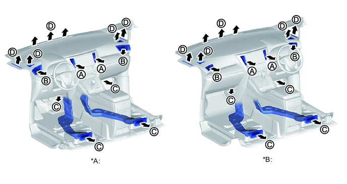
*A LHD Models *B RHD Models 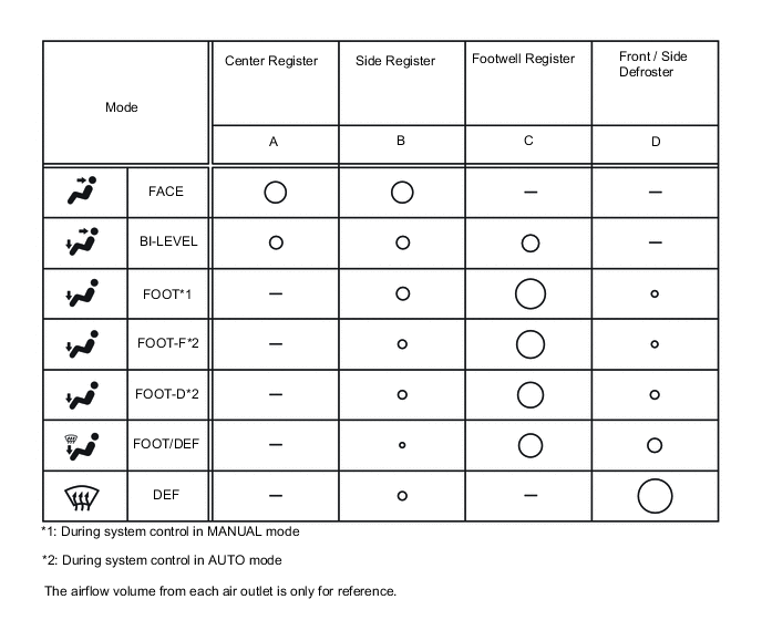
-